Biostar P4M80 PRO-M7 The P4M800 PRO-M7 manual - Page 16
JUSB2/JUSB3: Headers for USB 2.0 Ports at Front Panel, JPANEL1: Front Panel Header
 |
View all Biostar P4M80 PRO-M7 manuals
Add to My Manuals
Save this manual to your list of manuals |
Page 16 highlights
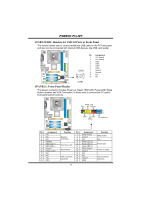
P4M800 Pro-M7 JUSB2/JUSB3: Headers for USB 2.0 Ports at Front Panel This header allows user to connect additional USB cable on the PC front panel, and also can be connected with internal USB devices, like USB card reader. JUSB2 2 10 1 9 JUSB3 Pin Assignment 1 +5V (fused) 2 +5V (fused) 3 USB- 4 USB- 5 USB+ 6 USB+ 7 Ground 8 Ground 9 Key 10 NC JPANEL1: Front Panel Header This 24-pin connector includes Power-on, Reset, HDD LED, Power LED, Sleep button, speaker and IrDA Connection. It allows user to connect the PC case's front panel switch functions. PWR_LED SLP On/Off ++ 2 1 +- SPK RST HLED 24 23 IR (optional) Pin Assignment 1 +5V 3 N/A 5 N/A 7 Speaker 9 HDD LED (+) 11 HDD LED (-) 13 Ground 15 Reset control 17 N/A 19 N/A 21 +5V 23 IRTX Function Pin Assignment 2 Sleep control Speaker Connector 4 Ground 6 N/A 8 Power LED (+) Hard drive LED 10 12 Power LED (+) Power LED (-) Reset button 14 Power button 16 Ground 18 N/A IrDA Connector (optional) 20 22 Key Ground 24 IRRX 14 Function Sleep button N/A Power LED Power-on button IrDA Connector (optional)
-
 1
1 -
2
-
3
-
4
-
5
-
6
-
7
-
8
-
9
-
10
-
 11
11 -
 12
12 -
 13
13 -
 14
14 -
 15
15 -
 16
16 -
 17
17 -
 18
18 -
 19
19 -
 20
20 -
 21
21 -
22
-
23
-
24
-
25
-
26
-
27
-
28
-
29
-
30
-
31
 |
 |
