Biostar P4M890-M7 TE Setup Manual
Biostar P4M890-M7 TE Manual
 |
View all Biostar P4M890-M7 TE manuals
Add to My Manuals
Save this manual to your list of manuals |
Biostar P4M890-M7 TE manual content summary:
- Biostar P4M890-M7 TE | Setup Manual - Page 1
P4M900-M7 SE/P4M890-M7 TE Setup Manual FCC Information and Copyright This equipment has been tested and radiate radio frequency energy and, if not installed and used in accordance with the instructions, may cause harmful interference to radio communications. There is no guarantee that interference - Biostar P4M890-M7 TE | Setup Manual - Page 2
Motherboard Features 4 1.4 Rear Panel Connectors 5 1.5 Motherboard Layout 6 Chapter 2: Hardware Installation 7 2.1 Installing Central Processing Unit (CPU 20 5.1 Driver Installation Note 20 5.2 Award BIOS Beep Code 21 5.3 Extra Information 21 5.4 Troubleshooting 22 Chapter - Biostar P4M890-M7 TE | Setup Manual - Page 3
M7 SE/P4M890-M7 TE CHAPTER 1: INTRODUCTION 1.1 BEFORE YOU START Thank you for choosing our product. Before you start installing the motherboard, please make sure you follow the instructions HDD Cable X 1 Installation Guide X 1 Fully Setup Driver CD X 1 (full version manual files inside) Rear I/O - Biostar P4M890-M7 TE | Setup Manual - Page 4
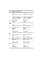
Motherboard Manual 1.3 MOTHERBOARD FEATURES CPU FSB P4M900-M7 SE P4M890-M7 TE LGA 775 LGA 775 Intel Core2Duo/ Pentium 4 / Pentium D / Intel Core2Duo/ Pentium 4 / Pentium D / Celeron D / Celeron 4xx processor up to 3.8 Celeron D / Celeron 4xx processor up to 3.8 GHz GHz Supports Hyper - Biostar P4M890-M7 TE | Setup Manual - Page 5
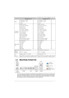
PS/2 Mouse x1 Serial Port x1 VGA Port x1 LAN port x1 USB Port x4 Audio Jack x3 Board Size 190 mm (W) x 244 mm (L) 190 mm (W) x 244 mm (L) Special Feature RAID 0 / 1 support RAID 0 / 1 support OS Support Windows 2000 / XP / VISTA Windows 2000 / XP Biostar Reserves the right to add - Biostar P4M890-M7 TE | Setup Manual - Page 6
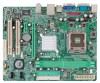
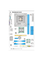
Motherboard Manual 1.5 MOTHERBOARD LAYOUT JKBMS1 LGA775 JCFAN1 COJMC1OM1 CPU1 JATXPWR1 JVGA1 DIMM1 DIMM2 JPRNT1 JUSB1 JUSBLAN1 JATXPWR2 JAUDIO1 LAN P4M900 or P4M890 PCI-EX16 Super I/O BAT1 PCI-EX1_1 JCDIN1 Codec JAUDIOF1 PCI1 PCI2 BIOS JUSB2 JUSB3 FDD1 Note: ■ rep resen ts th e 1 - Biostar P4M890-M7 TE | Setup Manual - Page 7
P4M900-M7 SE/P4M890-M7 TE CHAPTER 2: HARDWARE INSTALLATION 2.1 INSTALLING CENTRAL PROCESSING UNIT (CPU) Special Notice: Remove Pin Cap before installation, and make good preservation for future use. When the CPU is removed, cover the Pin Cap on the empty socket to ensure pin legs won't be damaged. - Biostar P4M890-M7 TE | Setup Manual - Page 8
Motherboard Manual Step 2: Look for the triangular cut edge on socket, and the golden dot on CPU should point forwards this triangular cut edge. The CPU will fit only in the correct orientation. Step 2-1: Step 2-2: Step 3: Hold the CPU down firmly, and then lower the lever to locked position to - Biostar P4M890-M7 TE | Setup Manual - Page 9
P4M900-M7 SE/P4M890-M7 TE 2.2 FAN HEADERS These fan headers support cooling-fans built in the computer. The fan cable and connector may be different according to the fan manufacturer. Connect the fan cable to the connector while matching the black wire to pin#1. JCFAN1: CPU Fan Header 4 1 Pin - Biostar P4M890-M7 TE | Setup Manual - Page 10
Motherboard Manual 2.3 INSTALLING SYSTEM MEMORY A. Memory Modules DIMM1 DIMM2 1. Unlock a DIMM slot by pressing the retaining clips outward. Align a DIMM on the slot such that the notch - Biostar P4M890-M7 TE | Setup Manual - Page 11
P4M900-M7 SE/P4M890-M7 TE 2.4 CONNECTORS AND SLOTS FDD1: Floppy Disk Connector The motherboard provides a standard floppy disk connector that supports 360K, 720K, 1.2M, 1.44M and 2.88M floppy disk types. This connector supports the provided floppy drive ribbon cable. 2 34 1 33 IDE1/IDE2: Hard - Biostar P4M890-M7 TE | Setup Manual - Page 12
Motherboard Manual PCI-EX16 bandwidth up to 250MB/s per direction; 500MB/s in total. - PCI-Express supports a raw bit-rate of 2.5Gb/s on the data pins. - 2X bandwidth PCI-EX1_1 PCI1/PCI2: Peripheral Component Interconnect Slots This motherboard is equipped with 2 standard PCI slots. PCI stands for - Biostar P4M890-M7 TE | Setup Manual - Page 13
P4M900-M7 SE/P4M890-M7 TE CHAPTER 3: HEADERS & JUMPERS SETUP 3.1 HOW TO SETUP JUMPERS The illustration shows how to set up jumpers. When the jumper cap is placed on pins, the - Biostar P4M890-M7 TE | Setup Manual - Page 14
Motherboard Manual ATX Power Source Connector: JATXPWR1 JATXPWR1 allows user to connect 24-pin power 12 +3.3V JATXPWR2: ATX Power Source Connector By connecting this connector, it will provide +12V to CPU power circuit. Pin Assignment 1 4 1 +12V 2 +12V 2 3 3 Ground 4 Ground 14 - Biostar P4M890-M7 TE | Setup Manual - Page 15
P4M900-M7 SE/P4M890-M7 TE JUSB2/JUSB3: Headers for USB 2.0 Ports at Front Panel This header allows user to connect additional USB cable on the PC front panel, and also can be connected with internal USB devices, like USB card reader. Pin Assignment 1 +5V (fused) 2 +5V (fused) 3 USB4 USB5 USB+ 6 USB+ - Biostar P4M890-M7 TE | Setup Manual - Page 16
Motherboard Manual JCDIN1: CD-ROM Audio-in Connector This connector allows user to connect the audio source from the variaty devices, like CD-ROM, DVD-ROM, PCI sound card, PCI TV turner card etc. Pin Assignment 1 Left Channel Input 2 Ground 3 Ground 4 Right Channel Input 4 1 JCMOS1: Clear CMOS - Biostar P4M890-M7 TE | Setup Manual - Page 17
P4M900-M7 SE/P4M890-M7 TE JPRNT1: Printer Port Connector This header allows you to connector printer on the PC. 25 2 1 Pin Assignment 1 -Strobe 2 -ALF 3 Data 0 4 -Error 5 Data 1 6 -Init 7 Data 2 8 -Scltin 9 - Biostar P4M890-M7 TE | Setup Manual - Page 18
Motherboard Manual CHAPTER 4: RAID FUNCTIONS 4.1 OPERATION SYSTEM Supports Windows XP Home/Professional Edition, and Windows 2000 Professional. 4.2 RAID ARRAYS RAID supports the following types of RAID arrays: RAID 0: RAID 0 defines a disk striping scheme that improves disk read and write times - Biostar P4M890-M7 TE | Setup Manual - Page 19
P4M900-M7 SE/P4M890-M7 TE RAID 1: Every read and write is actually carried out in parallel can be applied for high-availability solutions, or as a form of automatic backup that eliminates tedious manual backups to more expensive and less reliable media. Features and Benefits Drives: Minimum 2, and - Biostar P4M890-M7 TE | Setup Manual - Page 20
for better system performance. You will see the following window after you insert the CD The setup guide will auto detect your motherboard and operating system. Note: If this window didn't show up after you insert the Driver CD, please use file browser to locate and execute the file SETUP.EXE under - Biostar P4M890-M7 TE | Setup Manual - Page 21
P4M900-M7 SE/P4M890-M7 TE 5.2 AWARD BIOS BEEP CODE Beep Sound Meaning One long beep followed by two short Video card not found or video card beeps memory bad High-low siren sound CPU overheated System will shut down automatically One Short beep when system boot-up No error found during POST - Biostar P4M890-M7 TE | Setup Manual - Page 22
Motherboard Manual 5.4 TROUBLESHOOTING Probable Solution 1. No power to the system at all 1. Make sure power cable is Power light don't illuminate, fan securely plugged in. inside power supply does not turn 2. Replace cable. on. 3. Contact technical support Failure." Review system's - Biostar P4M890-M7 TE | Setup Manual - Page 23
-M7 SE/P4M890-M7 TE BIOS model and chipsets. In addition, the frequency status of CPU, memory, VGA and PCI along with the CPU speed Support: Windows 98 SE, Windows Me, Windows 2000, Windows XP DirectX: DirectX 8.1 or above. (The Windows XP operating system includes DirectX 8.1. If you use Windows XP - Biostar P4M890-M7 TE | Setup Manual - Page 24
Motherboard Manual 6.3 INSTALLATION 1. Execute the setup execution file, and then the following dialog will pop up. Please click "Next" "Finish" button. Usage: The following figures are only for reference, the screen printed in this user manual will change according to your motherboard on hand. 24 - Biostar P4M890-M7 TE | Setup Manual - Page 25
6.4 WARPSPEEDER™ III P4M900-M7 SE/P4M890-M7 TE 1. Desktop Icon: After the [WarpSpeeder™ III] has been installed, a [ ; the utility's first window you will see is Main Panel. Main Panel contains features as follows: a. Display the CPU Speed, CPU external clock, Memory clock, VGA clock, and PCI clock - Biostar P4M890-M7 TE | Setup Manual - Page 26
Motherboard Manual 3. Overclock/Overvoltage Panel Click the Overclock/Overvoltage button in the Main Panel, the button will be highlighted and the Overclock/Overvoltage Panel will show up - Biostar P4M890-M7 TE | Setup Manual - Page 27
M7 SE/P4M890-M7 TE Overclock Panel contains these features: a. "Auto-Overclock": User can click this button and [WarpSpeeder™ III] will set the best will load the previously verified best and stable frequency. b. "Verify": If you use the "Manual Adjust" bar to adjust the CPU frequency, then you can - Biostar P4M890-M7 TE | Setup Manual - Page 28
Motherboard Manual Overvoltage Panel contains these features: a. "CPU Voltage": This function allows user to adjust CPU voltage. Click on "+" to increase or "-" to decrease the CPU voltage. b. "Memory Voltage": This function allows user to adjust Memory voltage. Click on "+" to increase or "-" to - Biostar P4M890-M7 TE | Setup Manual - Page 29
P4M900-M7 SE/P4M890-M7 TE 5. About Panel Click the "about" button in Main Panel, the button will be highlighted and the About Panel will show up as the following figure. - Biostar P4M890-M7 TE | Setup Manual - Page 30
Motherboard Manual APPENDENCIES: SPEC IN OTHER LANGUAGE GERMAN CPU P4M900-M7 SE P4M890-M7 TE LGA 775 LGA 775 Intel Core2Duo/ Pentium 4 / Pentium D / Intel Core2Duo/ MHz VIA P4M900 VIA VT8237A 533 / 800 / 1066 MHz VIA P4M890 VIA VT8237A Grafik Chrome9 HC 3D / 2D Graphics Max. 256MB gemeinsam - Biostar P4M890-M7 TE | Setup Manual - Page 31
P4M900-M7 SE/P4M890-M7 TE P4M900-M7 SE P4M890-M7 TE LAN PHY Realtek RTL 8201CL PHY/ Atheros AR8012 PHY (optional) 10 / 100 Mb/s Auto-Negotiation Halb-/ Vollduplex-Funktion Realtek RTL 8201CL PHY/ Atheros AR8012 PHY (optional) 10 / 100 Mb/s Auto-Negotiation Halb-/ Vollduplex-Funktion Audio-Code - Biostar P4M890-M7 TE | Setup Manual - Page 32
Motherboard Manual FRANCE P4M900-M7 SE P4M890-M7 TE LGA 775 LGA 775 Processeurs Intel Core2Duo/ Pentium 4 / Processeurs Intel Core2Duo/ Pentium 4 leur IDE intégré Contrôleur IDE intégré Mode principale de Bus Ultra DMA 33 / 66 / Mode principale de Bus Ultra DMA 33 / 66 / IDE 100 / 133 100 - Biostar P4M890-M7 TE | Setup Manual - Page 33
série x1 Port VGA x1 Port LAN x1 Port USB x4 Fiche audio x3 Dimension s de la 190 mm (l) X 244 mm (H) carte 190 mm (l) X 244 mm (H) Fonctionna lités Prise en charge RAID 0 / 1 spéciales Prise en charge RAID 0 / 1 Support SE Windows 2K / XP / VISTA Biostar se réserve le droit - Biostar P4M890-M7 TE | Setup Manual - Page 34
Motherboard Manual ITALIAN P4M900-M7 SE P4M890-M7 TE CPU LGA 775 LGA 775 Processore Intel Core2Duo/ Pentium 4 / Processore Intel Core2Duo/ VIA P4M890 VIA VT8237A Grafica Chrome9 HC 3D / 2D Graphics La memoria video condivisa massima è di 256MB Unichrome Pro IGP La memoria video condivisa - Biostar P4M890-M7 TE | Setup Manual - Page 35
-M7 TE LAN PHY P4M900-M7 SE Realtek RTL 8201CL PHY/ Atheros AR8012 PHY (optional) Negoziazione automatica 10 / 100 Mb/s Capacità Half / Full Duplex P4M890-M7 TE Realtek RTL 8201CL PHY/ Atheros AR8012 PHY (optional) Negoziazione automatica 10 / 100 Mb/s Capacità Half / Full Duplex Codec audio - Biostar P4M890-M7 TE | Setup Manual - Page 36
Motherboard Manual SPANISH CPU FSB Conjunto de chips Gráficos P4M900-M7 SE P4M890-M7 TE LGA 775 LGA 775 Procesador Intel Core2Duo / Pentium 4 / Procesador Intel Core2Duo / Pentium 4 / Pentium D / Celeron D / Celeron 4xx hasta Pentium D / Celeron D / Celeron 4xx hasta 3,8 GHz 3,8 GHz - Biostar P4M890-M7 TE | Setup Manual - Page 37
-M7 SE/P4M890-M7 TE P4M900-M7 SE Realtek RTL 8201CL PHY/ Atheros AR8012 PHY (opcional) Red Local Negociación de 10 / 100 Mb/s Funciones Half / Full dúplex P4M890-M7 TE Realtek RTL 8201CL PHY/ Atheros AR8012 PHY (opcional) Negociación de 10 / 100 Mb/s Funciones Half / Full dúplex ALC662 Códecs de - Biostar P4M890-M7 TE | Setup Manual - Page 38
Motherboard Manual PORTUGUESE P4M900-M7 SE P4M890-M7 TE CPU LGA 775 LGA 775 Processador de 256MB /512 MB / 1 GB / 2GB DDR2 de 256MB /512 MB / 1 GB / 2GB Capacidade máxima de memória: 4 GB Capacidade máxima de memória: 4 GB Módulo de memória DDR2 de canal simples Módulo de memória DDR2 de - Biostar P4M890-M7 TE | Setup Manual - Page 39
-M7 SE/P4M890-M7 TE P4M900-M7 SE P4M890-M7 TE LAN PHY Realtek RTL 8201CL PHY/ Atheros AR8012 PHY (opcional) Auto negociação de 10 / 100 MB/s Capacidade semi/full-duplex Realtek RTL 8201CL PHY/ Atheros AR8012 PHY (opcional) Auto negociação de 10 / 100 MB/s Capacidade semi/full-duplex Codec de - Biostar P4M890-M7 TE | Setup Manual - Page 40
Motherboard Manual POLISH Procesor P4M900-M7 SE P4M890-M7 TE LGA 775 LGA 775 Procesor Intel Core2Duo/ Pentium 4 / Procesor Intel video wynosi 256MB Unichrome Pro IGP Maks. wielkość współdzielonej pamięci video wynosi 64MB Pamięć główna Gniazda DDR2 DIMM x 2 Obsługa DDR2 533 / 667 Każde - Biostar P4M890-M7 TE | Setup Manual - Page 41
Port VGA x1 I/O Port LAN x1 Port LAN x1 Port USB x4 Port USB x4 Gniazdo audio x3 Gniazdo audio x3 Wymiary 190 mm (S) X 244 mm (W) płyty 190 mm (S) X 244 mm (W) Funkcje Obsługa RAID 0 / 1 specjalne Obsługa RAID 0 / 1 Obsluga Windows 2K / XP / VISTA Windows 2K / XP systemu Biostar - Biostar P4M890-M7 TE | Setup Manual - Page 42
Motherboard Manual RUSSIAN P4M900-M7 SE P4M890-M7 TE LGA 775 LGA 775 Intel Core2Duo/ Pentium 4 Intel Core2Duo/ Pentium 4 / CPU Pentium D / Celeron D / Celeron 4xx до 3.8 Hyper-Threading / Execute Disable Bit / Enhanced Intel SpeedStep® / Intel Architecture-64 / Extended Memory 64 - Biostar P4M890-M7 TE | Setup Manual - Page 43
VGA Порт LAN USB x1 x1 x4 Мышь PS/2 x1 x1 Порт VGA x1 Порт LAN x1 USB-порт x4 x3 x3 190 мм (Ш) X 244 мм (В) 190 мм (Ш) X 244 мм (В) ные RAID 0 / 1 RAID 0 / 1 стики Windows 2K / XP / VISTA Windows 2K / XP OS Biostar OS Biostar - Biostar P4M890-M7 TE | Setup Manual - Page 44
Motherboard Manual ARABIC P4M890-M7 TE P4M900-M7 SE LGA 775 LGA 775 Intel Core2Duo/ Pentium 4 / Pentium Intel Core2Duo/ Pentium 4 / Pentium D / Celeron D / Celeron 4xx 3.8 D / Celeron D / Celeron 4xx 3.8 Hyper-Threading / Execute Disable Hyper- - Biostar P4M890-M7 TE | Setup Manual - Page 45
P4M900-M7 SE/P4M890-M7 TE P4M890-M7 TE P4M900-M7 SE Atheros AR8012 PHY 10/100 Atheros AR8012 PHY 10 VGA 1 4 USB 3 190 244 X RAID 0 / 1 RAID 0 / 1 Windows 2K / XP Windows 2K / XP / VISTA Biostar Biostar - Biostar P4M890-M7 TE | Setup Manual - Page 46
Motherboard Manual JAPANESE P4M900-M7 SE P4M890-M7 TE CPU LGA 775 LGA 775 Intel Core2Duo/ Pentium 4 / Pentium D / Intel Core2Duo 800 / 1066 MHz 533 / 800 / 1066 MHz VIA P4M900 ト VIA VT8237A VIA P4M890 VIA VT8237A Chrome9 HC 3D / 2D Graphics クス 256MBです Unichrome Pro IGP 64MBです - Biostar P4M890-M7 TE | Setup Manual - Page 47
P4M900-M7 SE/P4M890-M7 TE LAN PHY Codec P4M900-M7 SE Realtek RTL 8201CL PHY/ Atheros AR8012 PHY 10 / 100 Mb ALC662 5.1 PCIスロット x2 P4M890-M7 TE Realtek RTL 8201CL PHY/ Atheros AR8012 PHY 10 / 100 Mb ALC662 5.1 PCIスロット x2 PCI Express x16スロット x1 PCI
-
 1
1 -
 2
2 -
 3
3 -
 4
4 -
 5
5 -
 6
6 -
 7
7 -
8
-
9
-
10
-
11
-
12
-
13
-
14
-
15
-
16
-
17
-
18
-
19
-
20
-
21
-
22
-
23
-
24
-
25
-
26
-
27
-
28
-
29
-
30
-
31
-
32
-
33
-
34
-
35
-
36
-
37
-
38
-
39
-
40
-
41
-
42
-
43
-
44
-
45
-
46
-
47
 |
 |

P4M900-M7 SE/P4M890-M7 TE
Setup Manual
FCC Information and Copyright
This equipment has been tested and found to comply with the limits of a Class
B digital device, pursuant to Part 15 of the FCC Rules. These limits are designed
to provide reasonable protection against harmful interference in a residential
installation. This equipment generates, uses, and can radiate radio frequency
energy and, if not installed and used in accordance with the instructions, may
cause harmful interference to radio communications. There is no guarantee
that interference will not occur in a particular installation.
The vendor makes no representations or warranties with respect to the
contents here and specially disclaims any implied warranties of merchantability
or fitness for any purpose. Further the vendor reserves the right to revise this
publication and to make changes to the contents here without obligation to
notify any party beforehand.
Duplication of this publication, in part or in whole, is not allowed without first
obtaining the vendor’s approval in writing.
The content of this user’s manual is subject to be changed without notice and
we will not be responsible for any mistakes found in this user’s manual. All the
brand and product names are trademarks of their respective companies.