Biostar P4M900-M4 Setup Manual
Biostar P4M900-M4 Manual
 |
View all Biostar P4M900-M4 manuals
Add to My Manuals
Save this manual to your list of manuals |
Biostar P4M900-M4 manual content summary:
- Biostar P4M900-M4 | Setup Manual - Page 1
P4M900-M4 Setup Manual FCC Information and Copyright This equipment has been tested and found to comply radiate radio frequency energy and, if not installed and used in accordance with the instructions, may cause harmful interference to radio communications. There is no guarantee that interference - Biostar P4M900-M4 | Setup Manual - Page 2
6.x)...6 Motherboard Layout...7 Installing Central Processing Unit (CPU) ...8 Fan Headers ...9 Installing System Memory ...10 Connectors and Slots ...11 How to Setup Jumpers ...13 Detail Settings ...13 Driver Installation Note...19 Award BIOS Beep Code ...20 Extra Information...20 Troubleshooting - Biostar P4M900-M4 | Setup Manual - Page 3
P4M900-M4 CHAPTER 1: INTRODUCTION 1.1 BEFORE YOU START Thank you for choosing our product. Before you start installing the motherboard, please make sure you follow the instructions water. 1.2 PACKAGE CHECKLIST HDD Cable X 1 User's Manual X 1 Fully Setup Driver CD X 1 Rear I/O Panel for ATX Case X - Biostar P4M900-M4 | Setup Manual - Page 4
Motherboard Manual 1.3 MOTHERBOARD FEATURES Ver 5.x Socket 478 Socket 478 Ver 6.x Intel Pent ium 4 / Celeron D processor up to Intel Pent ium 4 / Celeron D processor up to CPU 3.4 GHz (Do not support Willamette CPU.) 3.4 GHz (Do not support Willamette CPU.) Supports Hyper Threading technology - Biostar P4M900-M4 | Setup Manual - Page 5
S/PDIF out connector CPU Fan header System Fan header Clear CMOS header USB connector Power Connector (24pin) Power Connector (4pin) PS/2 Keyboard PS/2 Mouse Back Panel I/O Serial Port VGA Port LAN port USB Port Audio Jack Board Size 190 mm (W) x 244 mm (L) OS Support Windows 2000 / XP / VISTA x1 x1 - Biostar P4M900-M4 | Setup Manual - Page 6
/2 Mouse REAR PANEL CONNECTORS (FOR VER 6.X) LAN Line In/ Surround Line Out Mic In 1/ Bass/ Center PS/2 Keyboar d COM1 VGA USBX2 USBX2 Since the audio chip supports High Definition Audio Specification, the function of each audio jack can be defined by software. The input / output function of - Biostar P4M900-M4 | Setup Manual - Page 7
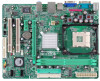
P4M900-M4 1.6 JKBMS1 MOTHERBOARD LAYOUT JCFAN1 PU Socket 478 M1 JCO CPU1 JPRNT1 JATXPWR1 DIMM1 JUSBV1 JATXPWR2 JUSB1 IDE1 JUSB2 JAUDIO1 (for Ver 5.x) JAUDIO2 (for Ver 6.x) LAN PCI-EX16 Super I/O PCI-EX1_1 BAT1 JSATA2 PCI1 BIOS JCDIN1 JUSB3 VIA VT8237A JSATA1 PCI2 Codec JAUDIOF1 - Biostar P4M900-M4 | Setup Manual - Page 8
Motherboard Manual CHAPTER 2: HARDWARE INSTALLATION 2.1 INSTALLING CENTRAL PROCESSING UNIT (CPU) Step 1: Pull the lever sideways away from the socket and then raise the lever up to a 90-degree angle. Step 2: Look for the white dot/cut edge. The white dot/cut edge should point - Biostar P4M900-M4 | Setup Manual - Page 9
P4M900-M4 2.2 FAN HEADERS These fan headers support cooling-fans built in the computer. The fan cable and connector may be different according to the fan manufacturer. Connect the fan cable to the connector while matching the black wire to pin#1. JCFAN1: CPU Fan Header Pin 1 2 3 Assignment - Biostar P4M900-M4 | Setup Manual - Page 10
Motherboard Manual 2.3 INSTALLING SYSTEM MEMORY A. Memory Modules 1. Unlock a DIMM slot by pressing the retaining clips outward. chip snap back in place and the DIMM is properly seated. B. Memory Capacity DIMM Socket Location DIMM1 DIMM2 DDR Module 256MB/512MB/1GB/2GB 256MB/512MB/1GB/2GB Total - Biostar P4M900-M4 | Setup Manual - Page 11
P4M900-M4 2.4 CONNECTORS AND SLOTS FDD1: Floppy Disk Connector The motherboard provides a standard floppy disk connector that supports 360K, 720K, 1.2M, 1.44M and 2.88M floppy disk types. This connector supports the provided floppy drive ribbon cables. 2 34 1 33 IDE1/IDE2: Hard Disk - Biostar P4M900-M4 | Setup Manual - Page 12
; 500MB/s in total. PCI-Express supports a raw bit-rate of 2.5Gb/s on the data pins. 2X bandwidth over the traditional PCI architecture. PCI-EX1_1: PCI-Express x1 Slot - PCI-EX16 PCI-EX1_1 PCI1~PCI2: Peripheral Component Interconnect Slots This motherboard is equipped with 2 standard PCI slots - Biostar P4M900-M4 | Setup Manual - Page 13
P4M900-M4 CHAPTER 3: HEADERS & JUMPERS SETUP 3.1 HOW TO SETUP JUMPERS The illustration shows how to set up jumpers. When the jumper cap is placed on pins, the - Biostar P4M900-M4 | Setup Manual - Page 14
Motherboard Manual ATX Power Source Connector: JATXPWR1 JATXPWR1 allows user to connect 24-pin power connector on 12V +3.3V JATXPWR2: ATX Power Source Connector By connecting this connector, it will provide +12V to CPU power circuit. 1 2 4 3 Pin 1 2 3 4 Assignment +12V +12V Ground Ground 14 - Biostar P4M900-M4 | Setup Manual - Page 15
P4M900-M4 JUSB2/JUSB3: Headers for USB 2.0 Ports at Front Panel This header . 1 3 3 1 3 1 Pin 1-2 close JUSBV1 1 3 3 1 1 3 Pin 2-3 close JUSBV2 Note: In order to support this function "Power-On system via USB device," "JUSBV1/ JUSBV2" jumper cap should be placed on Pin 2-3 individually. 15 - Biostar P4M900-M4 | Setup Manual - Page 16
Motherboard Manual JAUDIOF1: Front Panel Audio Header This header allows user to connect the front audio output cable with the PC front panel. It will disable the output on back panel audio connectors. Pin 1 2 3 4 5 6 7 8 9 10 Assignment Mic Left in Ground Mic Right in GPIO Right line in Jack Sense - Biostar P4M900-M4 | Setup Manual - Page 17
P4M900-M4 JCMOS1: Clear CMOS Header By placing the jumper on pin2-3, it allows user to restore the BIOS safe setting and the CMOS data, please carefully follow the procedures to avoid damaging the motherboard. 1 3 Pin 1-2 Close: Normal Operation (default). 1 3 1 3 Pin 2-3 Close: Clear CMOS - Biostar P4M900-M4 | Setup Manual - Page 18
Motherboard Manual JPRNT1: Printer Port Connector This header allows you to connector printer on the PC. 25 2 1 Pin 1 2 3 4 5 6 7 8 9 10 11 12 13 Assignment -Strobe -ALF Data 0 -Error - Biostar P4M900-M4 | Setup Manual - Page 19
P4M900-M4 CHAPTER 4: USEFUL HELP 4.1 DRIVER INSTALLATION NOTE After you installed your operating system, please insert the Fully Setup Driver CD into your optical drive and install the driver for better system performance. You will see the following window after you insert the CD The setup guide - Biostar P4M900-M4 | Setup Manual - Page 20
BIOS contents are corrupted. A. BIOS Update In this Case, please follow the procedure below to restore the BIOS: 1. Make a bootable floppy disk. 2. Download the Flash Utility "AWDFLASH.exe" from the Biostar website: www.biostar.com.tw 3. Confirm motherboard model and download the respectively BIOS - Biostar P4M900-M4 | Setup Manual - Page 21
is over heated, the motherboard will shutdown automatically to avoid a damage of the CPU, and the system may not power on again. In this case, please double check: 1. The CPU cooler surface is placed evenly with the CPU surface. 2. CPU fan is rotated normally. 3. CPU fan speed is fulfilling with the - Biostar P4M900-M4 | Setup Manual - Page 22
Motherboard Manual 4.4 1. TROUBLESHOOTING Probable Solution No power to the system at all 1. Make sure power cable is Power light don't illuminate, fan securely plugged in. inside power supply does not turn 2. Replace cable. on. 3. Contact technical support. 2. Indicator light on keyboard does - Biostar P4M900-M4 | Setup Manual - Page 23
indicates the temperatures, voltage and CPU fan speed as well as the chipset information. Also, in the About panel, you can get detail descriptions about BIOS model and chipsets. In addition, the frequency status of CPU, memory, AGP and PCI along with the CPU speed are synchronically shown on our - Biostar P4M900-M4 | Setup Manual - Page 24
Motherboard Manual 5.3 INSTALLATION 1. Execute the setup execution file, and then the following dialog will pop up. Please click "Next" " button. Usage: The following figures are just only for reference, the screen printed in this user manual will change according to your motherboard on hand. 24 - Biostar P4M900-M4 | Setup Manual - Page 25
P4M900-M4 5.4 WARPSPEEDER™ Whenever the Tray Icon utility is launched, it will display a little tray icon on the right side of Windows Taskbar. 1. Tray Icon This utility is responsible for conveniently invoking [WarpSpeeder™] Utility. You can use the mouse by clicking the left button in order to - Biostar P4M900-M4 | Setup Manual - Page 26
the following figure; the utility's first window you will see is Main Panel. Main Panel contains features as follows: a. b. c. Display the CPU Speed, CPU external clock, Memory clock, AGP clock, and PCI clock information. Contains About, Voltage, Overclock, and Hardware Monitor Buttons for invoking - Biostar P4M900-M4 | Setup Manual - Page 27
P4M900-M4 3. Voltage Panel Click the Voltage button in Main Panel, the button will be highlighted and the Voltage Panel will slide out to up as the following figure. In this panel, you can decide to increase CPU core voltage and Memory voltage or not. The default setting is "No". If you want to get - Biostar P4M900-M4 | Setup Manual - Page 28
3MHz button": provide user the ability to do real-time overclock adjustment. Warning: Manually overclock is potentially dangerous, especially when the overclocking percentage is over 110 %. We strongly recommend you verify every speed you overclock by click the Verify button. Or, you can just click - Biostar P4M900-M4 | Setup Manual - Page 29
c. d. P4M900-M4 "Auto-overclock button": User can click this button and [WarpSpeeder™] will set the best and stable performance and frequency as the following figure. In this panel, you can get the real-time status information of your system. The information will be refreshed every 1 second. 29 - Biostar P4M900-M4 | Setup Manual - Page 30
Motherboard Manual 6. About Panel Click the "about" button in Main Panel, the button will be highlighted and the About Panel will slide out to up as the following figure. In this panel, you can get model name and detail information in hints of all the chipset that are related to overclocking. You - Biostar P4M900-M4 | Setup Manual - Page 31
P4M900-M4 This page is intentionally left blank. 31 - Biostar P4M900-M4 | Setup Manual - Page 32
Motherboard Manual APPENDENCIES: SPEC IN OTHER LANGUAGE GERMAN Ver 5.x Sockel 478 Intel Pentium 4 / Celeron D Prozessoren mit bis zu 3,4 GHz (Unterstützt keine CPU Willamette CPUs) Unterstützt Hyper-Threading Technology 95W power consumption. FSB Chipsatz 400 / 533 / 800 MHz VIA P4M900 VIA VT8237A - Biostar P4M900-M4 | Setup Manual - Page 33
P4M900-M4 Ver 5.x Realtek RTL 8201CL PHY LAN PHY 10 / 100 Mb/s Auto-Negotiation Halb-/ Vollduplex-Funktion Audio-Code c ALC883 Unterstützt High-Definition Audio 7.1-Kanal-Audioausgabe PCI-Steckplatz Steckplätze PCI Express x16 Steckplatz PCI Express x 1-Steckplatz Diskettenlaufwerkanschluss - Biostar P4M900-M4 | Setup Manual - Page 34
Motherboard Manual FRENCH Ver 5.x Socket 478 Processeurs Intel Pentium 4 / Celeron D UC Willamette) Prend en charge les technologies Hyper-Threading 95W power consumption. Bus frontal 400 / 533 / 800 MHz Chipset Graphique s VIA P4M900 VIA VT8237A Chrome9 HC 3D / 2D Graphics Mo ITE 8712F Fournit la - Biostar P4M900-M4 | Setup Manual - Page 35
P4M900-M4 Ver 5.x Realtek RTL 8201CL PHY LAN PHY 10 / 100 Mb/s négociation automatique Half / Full duplex capability Codec audio ALC883 Prise en charge de l'audio haute définition Sortie audio - Biostar P4M900-M4 | Setup Manual - Page 36
Motherboard Manual ITALIAN Ver 5.x Socket 478 a 3.4 GHz (Non supporta CPU Willamette) Supporto di Hyper-Threading 95W power consumption. FSB Chipset 400 / 533 / 800 MHz VIA P4M900 VIA VT8237A Chrome9 HC 3D / 2D Graphics Grafica La memoria video condivisa massima è di 256MB ITE 8712F Fornisce le - Biostar P4M900-M4 | Setup Manual - Page 37
P4M900-M4 Ver 5.x Codec audio ALC883 Supporto audio High-Definition (HD) Uscita audio 7.1 canali Alloggio PCI Alloggi Alloggio PCI Express x16 Alloggio PCI Express x1 Connettore floppy Connettore Porta stampante Connettore IDE Connettore SATA Connettore pannello frontale Connettore audio frontale - Biostar P4M900-M4 | Setup Manual - Page 38
Motherboard Manual SPANISH Ver 5.x Conector 478 Procesador Intel Pentium 4 / Celeron D CPU Admite Hyper-Threading 95W power consumption. FSB Conjunto de chips Gráficos 400 / 533 / 800 MHz VIA P4M900 VIA VT8237A Chrome9 HC 3D / 2D Graphics Memoria máx ima de vídeo compartida de 256MB ITE 8712F uso - Biostar P4M900-M4 | Setup Manual - Page 39
P4M900-M4 Ver . (A) X 244 Mm. (H) Windows 2K / XP / VISTA Biostar se reserva el derecho de añadir XP / VISTA Biostar se reserva el derecho de añadir o aviso previo. X1 X1 X1 X1 X1 X4 X3 X1 X1 X1 X2 X1 X2 X1 X1 X1 X1 X2 X2 X1 X1 X1 X1 Cabecera de vent ilador de CPU X1 Cabecera de vent ilador de CPU - Biostar P4M900-M4 | Setup Manual - Page 40
Motherboard Manual PORTUGUESE Ver 5.x Socket 478 3,4 GHz (não suporta a CPU Willamette) Suporta as tecnologias Hyper-Threading 95W power consumption. FSB Chipset Placa gráfica 400 / 533 / 800 MHz VIA P4M900 VIA VT8237A Chrome9 HC 3D / 2D Graphics MB ITE 8712F Proporciona as funcionalidades mais - Biostar P4M900-M4 | Setup Manual - Page 41
P4M900-M4 Ver 5.x ALC883 Codec de som Suporta a especificação High-Definition Audio CPU mm (A) Windows 2K / XP / VISTA x1 x1 x1 x1 x1 x4 x3 x1 x1 x2 x1 Conector para limpeza do CMOS x1 x1 x1 x2 x2 x1 x1 x1 x1 x1 x2 x1 x1 operativos A Biostar reserva-se o direito de adicionar A Biostar - Biostar P4M900-M4 | Setup Manual - Page 42
Motherboard Manual POLISH Ver 5.x Socket 478 Socket 478 Ver 6.x Procesor Intel Pentium 4 / Celeron D do 3,4 Procesor Intel Pentium 4 / Celeron D do 3,4 to use processors with 95W power consumption. FSB Chipset 400 / 533 / 800 MHz VIA P4M900 VIA VT8237A Chrome9 HC 3D / 2D Graphics Grafika Maks - Biostar P4M900-M4 | Setup Manual - Page 43
USB Złącze zasilania (24 pinowe) Złącze zasilania (4 pinowe) Klawiatura PS/2 Mysz PS/2 Port szeregowy Port VGA Port LAN Port USB Gniazdo audio 190 mm (S) X 244 mm (W) Windows 2K / XP / VISTA Biostar zastrzega sobie prawo dodawania lub odwo ływania obs ługi dowolnego x1 x2 x1 x1 x1 x1 x1 x1 x1 x4 x3 - Biostar P4M900-M4 | Setup Manual - Page 44
Motherboard Manual RUSSIAN Ver 5.x Гнездо 478 Процессор Intel Pentium 4 / Celeron D до 3.4 ГГц ( не поддерживает центральные процессоры Willamette) Поддержка технологий Hyper-Threading Technology *It is recommended to use processors with 95W power consumption. 400 / 533 / 800 МГц Ver 6.x Гнездо 478 - Biostar P4M900-M4 | Setup Manual - Page 45
P4M900-M4 Ver 5.x Realtek RTL 8201CL PHY Локальна я сеть Автоматическое согласование 10 / 100 Мб/с Частичная / полная дуплексная способность Звуковой кодек ALC883 Звуковая поддержка High-Definition 7.1канальный звуковой выход - Biostar P4M900-M4 | Setup Manual - Page 46
Motherboard Manual ARABIC Ver 6.x 478 Intel Pentium 4 / Celeron D 3.4 Willamette Hyper-Threading Technology Ver 5.x 478 Intel 533 / 800 VIA P4M900 VIA VT8237A Chrome9 HC 3D / 2D Graphics 256 95W power consumption 400 / 533 / 800 VIA P4M900 VIA VT8237A Chrome9 HC 3D - Biostar P4M900-M4 | Setup Manual - Page 47
P4M900-M4 Ver 6.x Realtek RTL 8201CL PHY ﺕﻔﺎوض ﺕ - Biostar P4M900-M4 | Setup Manual - Page 48
Motherboard Manual JAPANESE Ver 5.x Socket 478 Socket 478 Ver 6.x Intel Pent ium 4 / Celeron D processor up to Intel Pent ium 4 / Celeron D processor up to 3.4 GHz (Willamette CPU CPU ん) 3.4 GHz (Willamette CPU Hyper-Threading Technology Hyper-Threading Technology *It is recommended to use - Biostar P4M900-M4 | Setup Manual - Page 49
P4M900-M4 Ver 5.x Realtek RTL 8201CL PHY LAN PHY 10 / 100 Mb/秒のオートネゴシエーション 半/全二重機能 サウンド Codec ALC883 ハイデフィニションオーディオのサポート 7.1 チャンネルオーディオアウト PCIスロット スロット PCI Express x16スロット PCI Express x 1スロット フロッピーコネクタ プリンタポートコネクタ IDEコネクタ SATAコネクタ フロントパネルコネクタ フロントオーディオコネクタ オンボード CDインコネクタ コネクタ S/PDIFアウトコネクタ CPUファンヘッダ
-
 1
1 -
 2
2 -
 3
3 -
 4
4 -
 5
5 -
 6
6 -
 7
7 -
8
-
9
-
10
-
11
-
12
-
13
-
14
-
15
-
16
-
17
-
18
-
19
-
20
-
21
-
22
-
23
-
24
-
25
-
26
-
27
-
28
-
29
-
30
-
31
-
32
-
33
-
34
-
35
-
36
-
37
-
38
-
39
-
40
-
41
-
42
-
43
-
44
-
45
-
46
-
47
-
48
-
49
 |
 |

P4M900-M4 Setup Manual
FCC Information and Copyright
This equipment has been tested and found to comply with the limits of a Class
B digital device, pursuant to Part 15 of the FCC Rules. These limits are designed
to provide reasonable protection against harmful interference in a residential
installation. This equipment generates, uses, and can radiate radio frequency
energy and, if not installed and used in accordance with the instructions, may
cause harmful interference to radio communications. There is no guarantee
that interference will not occur in a particular installation.
The vendor makes no representations or warranties with respect to the
contents here and specially disclaims any implied warranties of merchantability
or fitness for any purpose. Further the vendor reserves the right to revise this
publication and to make changes to the contents here without obligation to
notify any party beforehand.
Duplication of this publication, in part or in whole, is not allowed without first
obtaining the vendor’s approval in writing.
The content of this user’s manual is subject to be changed without notice and
we will not be responsible for any mistakes found in this user’s manual. All the
brand and product names are trademarks of their respective companies.