Biostar P4M900-M4 Setup Manual - Page 6
Biostar P4M900-M4 Manual
 |
View all Biostar P4M900-M4 manuals
Add to My Manuals
Save this manual to your list of manuals |
Page 6 highlights
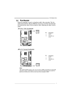
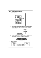
Motherboard Manual 1.4 REAR PANEL CONNECTORS (FOR VER 5.X) LAN AUDIO JACK PS/2 Mouse PS/2 Keyboard COM1 VGA USBX2 USBX2 Center Rear Side Line In Line Out Mic In 1.5 PS/2 Mouse REAR PANEL CONNECTORS (FOR VER 6.X) LAN Line In/ Surround Line Out Mic In 1/ Bass/ Center PS/2 Keyboar d COM1 VGA USBX2 USBX2 Since the audio chip supports High Definition Audio Specification, the function of each audio jack can be defined by software. The input / output function of each audio jack listed above represents the default setting. However, when connecting external microphone to the audio port, please use the Line In (blue) and Mic In (Pink) audio jack. 6
-
 1
1 -
 2
2 -
 3
3 -
 4
4 -
 5
5 -
 6
6 -
 7
7 -
 8
8 -
 9
9 -
 10
10 -
 11
11 -
 12
12 -
13
-
14
-
15
-
16
-
17
-
18
-
19
-
20
-
21
-
22
-
23
-
24
-
25
-
26
-
27
-
28
-
29
-
30
-
31
-
32
-
33
-
34
-
35
-
36
-
37
-
38
-
39
-
40
-
41
-
42
-
43
-
44
-
45
-
46
-
47
-
48
-
49
 |
 |
Motherboard Manual
6
1.4
R
EAR
P
ANEL
C
ONNECTORS
(
FOR
V
ER
5.
X
)
PS/2
Mouse
PS/2
Keyboard
USBX2
USBX2
LAN
COM1
VGA
Line In
Line Out
Mic In
Center
Rear
Side
AUDIO JACK
1.5
R
EAR
P
ANEL
C
ONNECTORS
(
FOR
V
ER
6.
X
)
PS/2
Mouse
PS/2
Keyboard
USBX2
USBX2
LAN
COM1
VGA
Line In/
Surround
Line Out
Mic In 1/
Bass/ Center
Since the audio chip supports High Definition Audio Specification, the function of each audio
jack can be defined by software. The input / output function of each audio jack listed above
represents the default setting. However, when connecting external microphone to the audio
port, please use the Line In (blue) and Mic In (Pink) audio jack.