Biostar P4TDQ P4TDQ user's manual - Page 7
Jumpers, Headers, Connectors & Slots, Power Connectors: JATXPW1 / JATXPWR2 - v motherboard
 |
View all Biostar P4TDQ manuals
Add to My Manuals
Save this manual to your list of manuals |
Page 7 highlights
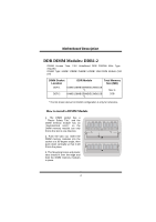
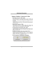
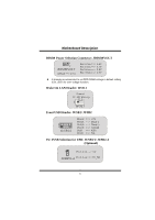
MMootthheerrbbooaarrdd DDeessccrriippttiioonn Jumpers, Headers, Connectors & Slots Hard Disk Connectors: IDE1/ IDE2 The motherboard has a 32-bit Enhanced PCI IDE Controller that provides PIO Mode 0~4, Bus Master, and Ultra DMA / 33/ 66/ 100 functionality. It has two HDD connectors IDE1 (primary) and IDE2 (secondary). The IDE connectors can connect a master and a slave drive, so you can connect up to four hard disk drives. The first hard drive should always be connected to IDE1. Floppy Disk Connector: FDD1 The motherboard provides a standard floppy disk connector that supports 360K, 720K, 1.2M, 1.44M and 2.88M floppy disk types. This connector supports the provided floppy drive ribbon cables. Communication Network Riser Slot: CNR1 The CNR specification is an open Industry Standard Architecture, and it defines a hardware scalable riser card interface, which supports audio, network and modem only. Peripheral Component Interconnect Slots: PCI1-3 This motherboard is equipped with 3 standard PCI slots. PCI stands for Peripheral Component Interconnect, and it is a bus standard for expansion cards, which has, supplanted the older ISA bus standard in most ports. This PCI slot is designated as 32 bits. Power Connectors: JATXPWR1/ JATXPWR2 JATXPWR2 JATXPWR1 (ATX 12V Power Conn.) (ATX Main Power Conn.) 5
-
 1
1 -
 2
2 -
 3
3 -
 4
4 -
 5
5 -
 6
6 -
 7
7 -
 8
8 -
 9
9 -
 10
10 -
 11
11 -
 12
12 -
13
-
14
-
15
-
16
-
17
-
18
-
19
-
20
-
21
 |
 |
