Biostar P4TPT P4TPT BIOS setup guide - Page 23
USB KB Wake-Up From S3 - motherboard manual
 |
View all Biostar P4TPT manuals
Add to My Manuals
Save this manual to your list of manuals |
Page 23 highlights
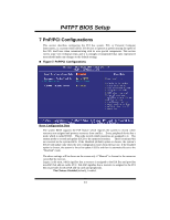
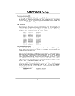
P4TPT BIOS Setup Power On by Ring An input signal on the serial Ring Indicator (RI) line (in other words, an incoming call on the modem) awakens the system from a soft off state. The Choices: Enabled, Disabled (default). Wake Up On LAN To use this function, you need a LAN add-on card which support power on function. It should also support the wake-up on LAN jumper. The Choices: Enabled, Disabled (default). USB KB Wake-Up From S3 This item allows you to enable/ disable USB KB wake up from S3. The Choices: Disabled (default), Enabled. Resume by Alarm This function is for setting date and time for your computer to boot up. During Disabled, you cannot use this function. During Enabled, Choose the Date and Time. Alarm: Date (of Month) Alarm You can choose which month the system will boot up. Time (hh:mm:ss) Alarm You can choose shat hour, minute and second the system will boot up. Note: If you have change the setting, you must let the system boot up until it goes to the operating system, before this functin will work. KBD Power On Function This item allows you to select the various functions of KB to Power on the system. The Choices: Disabled (Default), Enabled. KB Power On Password This item allows you to enter a password with at least 5 characters. HOT Key Power On This item allows you to set the hot key to power on system. The Choices: Ctrl-F1 (Default), Ctrl-F2, Ctrl-F3, Ctrl-F4, Ctrl-F5, Ctrl-F6, Ctrl-F7, Ctrl-F8, Ctrl-F9, Ctrl-F10, Ctrl-F11, Ctrl-F12. PWRON After PWR-Fail This field determines the action the system will automatically take when power is restored to a system that had lost power previously without any subsequent manual intervention. There are 3 sources that provide current to the CMOS area that retains these Power-On instructions; the motherboard battery (3V), the Power Supply (5VSB), and the Power Supply (3.3V). While AC is not supplying power, the motherboard uses the motherboard battery (3V). If AC power is supplied and the Power Supply is not turned on, 5VSB from the Power Supply is used. When the Power Supply is eventually turned on 3.3V from the Power Supply will be 22
-
 1
1 -
2
-
3
-
4
-
5
-
6
-
7
-
8
-
9
-
10
-
11
-
12
-
13
-
14
-
15
-
16
-
17
-
 18
18 -
 19
19 -
 20
20 -
 21
21 -
 22
22 -
 23
23 -
 24
24 -
 25
25 -
 26
26 -
 27
27 -
 28
28 -
29
 |
 |
