Biostar P4VMA-M P4VMA-M user's manual - Page 12
Installing DDR Module, How to set up Jumpers?, Jumpers, Headers, Connectors & Slots - motherboard
 |
View all Biostar P4VMA-M manuals
Add to My Manuals
Save this manual to your list of manuals |
Page 12 highlights
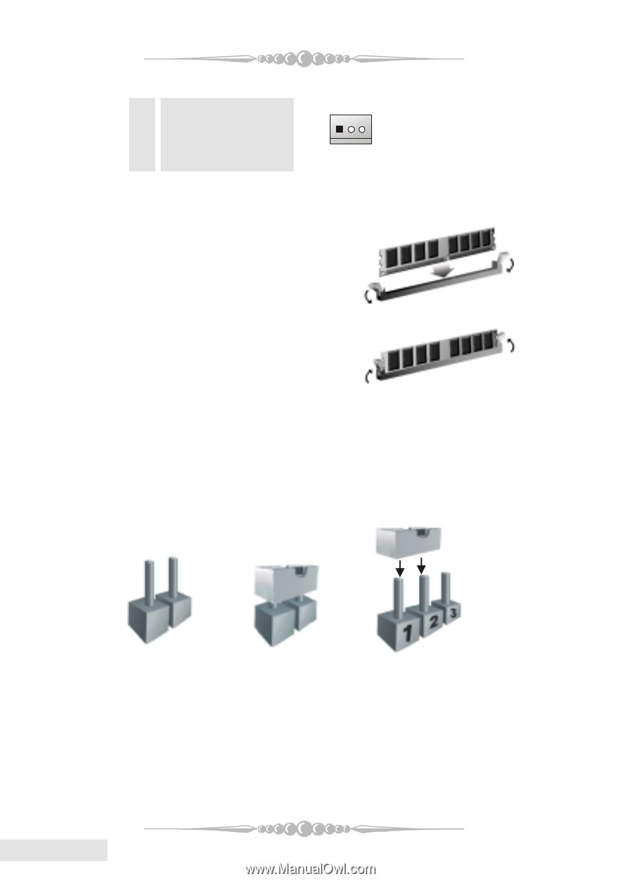
(2) System Fan Headers/North Bridge Fan Header: JSFAN1/(JNFAN1: optional) Pin Assignment 1 Ground 1 2 +12V 3 FAN RPM Rate Sense 3. Installing DDR Module 1. Unlock a DIMM slot by pressing the retaining clips outward. Align a DIMM to the slot in the way that the notch of the DIMM matches the break of the slot. 2. Insert the DIMM firmly and vertically into the slot until the retaining chip snap back in place and the Dimm is properly seated. 4. How to set up Jumpers? The illustration shows how to set up jumpers. When the Jumper cap is placed on pins, the jumper is "close". If no jumper cap is placed on the pins, the jumper is "open". The illustration shows a 3-pin jumper whose pin 1 and 2 are "close" when jumper cap is placed on these 2 pins. Jumper open Jumper close Pin1-2 close 5. Jumpers, Headers, Connectors & Slots: (1) Floppy Disk Connector: FDD1 The motherboard provides a standard floppy disk connector that supports 360K, 720K, 1.2M, 1.44M and 2.88M floppy disk types. This connector supports the provided floppy drive ribbon cables. English 12
-
 1
1 -
2
-
3
-
4
-
5
-
6
-
 7
7 -
 8
8 -
 9
9 -
 10
10 -
 11
11 -
 12
12 -
 13
13 -
 14
14 -
 15
15 -
 16
16 -
 17
17 -
18
-
19
-
20
-
21
-
22
-
23
-
24
-
25
-
26
-
27
-
28
-
29
-
30
-
31
-
32
 |
 |