Biostar TA790GX 128M Setup Manual
Biostar TA790GX 128M Manual
 |
View all Biostar TA790GX 128M manuals
Add to My Manuals
Save this manual to your list of manuals |
Biostar TA790GX 128M manual content summary:
- Biostar TA790GX 128M | Setup Manual - Page 1
TA790GX A2+/TA790GX A2+ SE/TA790GX 128M Setup Manual FCC Information and Copyright This equipment has been tested and found to a residential installation. This equipment generates, uses, and can radiate radio frequency energy and, if not installed and used in accordance with the instructions, may - Biostar TA790GX 128M | Setup Manual - Page 2
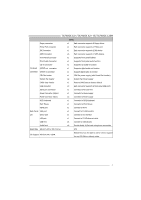
25 5.3 How RAID Works 25 Chapter 6: T-Series BIOS & Software 29 6.1 T-Series BIOS 29 6.2 T-Series Software 37 Chapter 7: Useful Help 47 7.1 Driver Installation Note 47 7.2 Extra Information 48 7.3 AMI BIOS Beep Code 49 7.4 Troubleshooting 50 Appendix: SPEC In Other Language - Biostar TA790GX 128M | Setup Manual - Page 3
TA790GX A2+/TA790GX A2+ SE/TA790GX 128M CHAPTER 1: INTRODUCTION 1.1 BEFORE YOU START Thank you for choosing our product. Before you start installing the motherboard, please make sure you follow the instructions Panel for ATX Case X 1 User's Manual X 1 Fully Setup Driver CD X 1 DCCFX-P2 Paddle Card X - Biostar TA790GX 128M | Setup Manual - Page 4
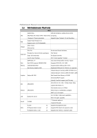
AM2+ CPU) Max Memory Capicity 16GB Registered DIMM and ECC DIMM is not supported Onboard side port memory 64MB (TA790GX A2+) Onboard side port memory 128MB (TA790GX 128M) Graphics Radeon HD 3300 Max Shared Video Memory is 512MB DX10/UVD/HDCP support (Hybrid) CrossFireX support (by ATI driver - Biostar TA790GX 128M | Setup Manual - Page 5
TA790GX A2+/TA790GX A2+ SE/TA790GX 128M SPEC Floppy connector x1 Each connector supports 2 Floppy drives Printer Port connector x1 Each connector supports 1 Printer port IDE Connector x1 Each connector supports 2 IDE device SATA Connector x6 Each connector supports 1 SATA devices Front - Biostar TA790GX 128M | Setup Manual - Page 6
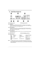
Motherboard Manual 1.4 REAR PANEL CONNECTORS X PS/2 Mouse Port Y PS/2 Keyboard Port Z HDMI Port The High-Definition Multimedia Interface (HDMI) is an all-digital audio/video interface capable of transmitting uncompressed streams to an AV receiver or any compatible digital audio Port _ Audio Jack - Biostar TA790GX 128M | Setup Manual - Page 7
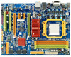
TA790GX A2+/TA790GX A2+ SE/TA790GX 128M 1.5 MOTHERBOARD LAYOUT JKBMS1 JATXPWR3 JCFAN1 JHDMI1 JATXPWR2 Socket AM2+ DVI VGA DIMMA1 DIMMB1 DIMMA2 DIMMB2 JUSB1 JUSBLAN1 JAUDIO2 J ATXPWR1 AMD 790GX JUSB V1 LAN JNFAN1 PEX16_2 PEX1_1 PEX1_2 BAT1 AMD SB750 SATA5-6 SATA3-4 IDE1 PEX16_1 - Biostar TA790GX 128M | Setup Manual - Page 8
Motherboard Manual CHAPTER 2: HARDWARE INSTALLATION 2.1 INSTALLING CENTRAL PROCESSING UNIT (CPU) Step 1: Remove the socket protection cap. Step 2: Pull the lever toward direction A from the socket and then raise the lever up to a 90-degree angle. Step 3: Look for the white triangle on socket, and - Biostar TA790GX 128M | Setup Manual - Page 9
A2+/TA790GX A2+ SE/TA790GX 128M Step 4: Hold the CPU down firmly, and then close the lever toward direct B to complete the installation. Step 5: Put the CPU Fan on the CPU and buckle it. Connect the CPU FAN power cable to the JCFAN1. This completes the installation. Note: Please update the BIOS - Biostar TA790GX 128M | Setup Manual - Page 10
Motherboard Manual 2.2 FAN HEADERS These fan headers support cooling-fans built in the computer. The fan cable and connector may be different according to the fan manufacturer. Connect the fan cable to the connector while matching the black wire to pin#1. JCFAN1: CPU Fan Header 1 4 Pin - Biostar TA790GX 128M | Setup Manual - Page 11
DIMMA 1 DIMMB 1 DIMMA 2 DIMMB 2 TA790GX A2+/TA790GX A2+ SE/TA790GX 128M 2.3 INSTALLING SYSTEM MEMORY A. DDR2 Modules 1. Unlock a DIMM slot by pressing the retaining clips outward. Align a DIMM on the slot such that the notch on the DIMM matches the break on the - Biostar TA790GX 128M | Setup Manual - Page 12
Motherboard Manual B. Memory Capacity DIMM Socket Location DIMMA1 DIMMB1 DIMMA2 DIMMB2 DDR2 Module 256MB/512MB/1GB/2GB/4GB 256MB/512MB/1GB/2GB/4GB 256MB/512MB/1GB/2GB/4GB 256MB/512MB/1GB/2GB/4GB Total Memory Size Max is 16GB. C. Dual Channel Memory installation To trigger the Dual Channel - Biostar TA790GX 128M | Setup Manual - Page 13
TA790GX A2+/TA790GX A2+ SE/TA790GX 128M 2.4 CONNECTORS AND SLOTS FDD1: Floppy Disk Connector The motherboard provides a standard floppy disk connector that supports 360K, 720K, 1.2M, 1.44M and 2.88M floppy disk types. This connector supports the provided floppy drive ribbon cables. 2 34 1 33 - Biostar TA790GX 128M | Setup Manual - Page 14
Motherboard Manual PEX16_1: PCI-Express Gen2 x16 Slot (x16/x8 Speed) - PCI-Express 2.0 compliant. - PCI-Express Gen2 supports a raw bit-rate of 5.0Gb/s on the data pins. - 2X bandwidth over the PCI-Express 1.1 architecture. - x16 Speed Mode: Maximum theoretical realized bandwidth of 8GB/s - Biostar TA790GX 128M | Setup Manual - Page 15
TA790GX A2+/TA790GX A2+ SE/TA790GX 128M PEX1_1/PEX1_2: PCI-Express Gen2 x1 Slots - PCI-Express 2.0 compliant. - Data transfer bandwidth up to 500MB/s per direction; 1GB/s in total. - PCI-Express Gen2 supports a raw bit-rate of 5.0Gb/s on the data pins. - 2X bandwidth over the PCI-Express 1.1 - Biostar TA790GX 128M | Setup Manual - Page 16
Motherboard Manual CHAPTER 3: HEADERS & JUMPERS SETUP 3.1 HOW TO SETUP JUMPERS The illustration shows how to set up jumpers. When the jumper cap is placed on pins, the jumper is "close", if not, that means the jumper is "open". Pin opened Pin closed 3.2 DETAIL SETTINGS Pin1-2 closed JPANEL1: - Biostar TA790GX 128M | Setup Manual - Page 17
TA790GX A2+/TA790GX A2+ SE/TA790GX 128M JATXPWR2: ATX Power Source Connector This connector allows 12 +3.3V JATXPWR3: ATX Power Source Connector By connecting this connector, it will provide +12V to CPU power circuit. 14 23 Pin Assignment 1 +12V 2 +12V 3 Ground 4 Ground Note: Before - Biostar TA790GX 128M | Setup Manual - Page 18
Motherboard Manual JATXPWR1: Auxiliary Power for Graphics This connector is an the jumper on pin2-3, it allows user to restore the BIOS safe setting and the CMOS data, please carefully follow the procedures to avoid damaging the motherboard. 13 Pin 1-2 Close: Normal Operation (default). 13 13 - Biostar TA790GX 128M | Setup Manual - Page 19
TA790GX A2+/TA790GX A2+ SE/TA790GX 128M SATA1-2/SATA3-4/SATA5-6: Serial ATA Connectors The motherboard has a PCI to SATA Controller with 6 channels SATA interface, it satisfies the SATA 2.0 spec and with transfer rate of 3.0Gb/s. SATA1-2 SATA3-4 SATA5-6 JUSB3~JUSB5: Headers for USB 2.0 Ports at - Biostar TA790GX 128M | Setup Manual - Page 20
Motherboard Manual JAUDIOF1: Front Panel Audio Header This header allows user to connect the front audio output cable with the PC front panel. This header allows only HD audio front panel connector; AC'97 connector is not acceptable. 2 10 Pin Assignment 1 Mic Left in 2 Ground 3 Mic Right in 4 - Biostar TA790GX 128M | Setup Manual - Page 21
TA790GX A2+/TA790GX A2+ SE/TA790GX 128M JCDIN1: CD-ROM Audio-in Connector This connector allows user to connect the audio source from the variaty devices, like CD-ROM, DVD-ROM, PCI sound card, PCI TV turner card etc. 14 Pin Assignment 1 Left Channel Input 2 Ground 3 - Biostar TA790GX 128M | Setup Manual - Page 22
Motherboard Manual JCOM1: Serial port Connector The motherboard has a Serial Port Connector for connecting RS-232 Port. 2 10 Pin Assignment 1 Carrier detect 2 Received data 3 Transmitted data 4 Data terminal ready 5 Signal ground 6 Data set ready 7 Request to send 8 Clear to send 9 Ring - Biostar TA790GX 128M | Setup Manual - Page 23
TA790GX A2+/TA790GX A2+ SE/TA790GX 128M On-Board LED Indicators There are 2 LED indicators on the motherboard to show system status. LED_D1 LED_D2 LED_D1 and LED_D2: These 2 LED indicate system power on diagnostics. Please refer to the table below for different messages: - Biostar TA790GX 128M | Setup Manual - Page 24
Motherboard Manual CHAPTER 4: (HYBRID) CROSSFIREX FUNCTION 4.1 CROSSFIREX REQUIREMENTS Only Windows XP/Vista supports CrossFireX (Dual Video) function. A pair of graphics cards with Radeon HD3650/HD3850/HD3870/HD4850/ HD4870 GPU. The graphics card driver should support CrossFireX technology. The - Biostar TA790GX 128M | Setup Manual - Page 25
TA790GX A2+/TA790GX A2+ SE/TA790GX 128M 4.3 HYBRID CROSSFIREX REQUIREMENTS Only Windows Vista supports Hybrid CrossFireX function. A graphics card with Radeon HD3450/HD3470 GPU. The graphics card driver should support card configuration program, choose "Hybrid CrossFireX" function. Installation - Biostar TA790GX 128M | Setup Manual - Page 26
Motherboard Manual 4.5 OPERATION MODES SUPPORTING LIST Operation Mode Single Card Model Radeon HD3650 O Radeon HD3850 O Radeon HD3870 O Radeon HD4850 O Radeon HD4870 O Radeon HD3450 O Radeon HD3470 O Radeon HD3870X2 O CrossFireX Hybrid CrossFireX O X O X O X O X O X X - Biostar TA790GX 128M | Setup Manual - Page 27
TA790GX A2+/TA790GX A2+ SE/TA790GX 128M CHAPTER 5: RAID FUNCTIONS 5.1 OPERATION SYSTEM Supports Windows XP and Windows VISTA. 5.2 RAID ARRAYS RAID supports the following types of RAID arrays: RAID 0: RAID 0 defines a disk striping scheme that improves disk read and write times for many applications. - Biostar TA790GX 128M | Setup Manual - Page 28
Motherboard Manual RAID 1: Every read and write is actually carried out in parallel across 2 disk drives in a RAID 1 array system. The mirrored (backup) copy of the data can reside on the same disk or on a second redundant drive in the array. RAID 1 provides a hot-standby copy of data if the active - Biostar TA790GX 128M | Setup Manual - Page 29
TA790GX A2+/TA790GX A2+ SE/TA790GX 128M RAID 1+0: RAID 1 drives can be stripped using RAID 0 techniques. Resulting in a RAID 1+0 solution for other RAID levels in an array, and allows for spare disks. Drawbacks: Requires twice the available disk space for data redundancy, the same as RAID level - Biostar TA790GX 128M | Setup Manual - Page 30
Motherboard Manual RAID 5: RAID 5 stripes both data and parity service. Benefits: An ideal combination of good performance, good fault tolerance, and high capacity and storage efficiency. Drawbacks: Individual block data transfer rate same as a single disk. Write performance can be CPU - Biostar TA790GX 128M | Setup Manual - Page 31
TA790GX A2+/TA790GX A2+ SE/TA790GX 128M CHAPTER 6: T-SERIES BIOS & SOFTWARE 6.1 T-SERIES BIOS T-Series BIOS Features Overclocking Navigator Engine (O.N.E.) Memory Integration Test (M.I.T., under Overclock Navigator Engine) BIO-Flasher: Update BIOS file from USB Flash Drive or FDD Self Recovery - Biostar TA790GX 128M | Setup Manual - Page 32
Motherboard Manual Manual Overclock System (M.O.S.) MOS is designed for experienced overclock users. It allows users to customize personal overclock settings. Main Advanced PCIPnP BIOS SETUP UTILITY Boot Chipset T-Series Exit T-Series Settings Options WARNING: Setting wrong values in - Biostar TA790GX 128M | Setup Manual - Page 33
A2+ SE/TA790GX 128M CPU Frequency CPU Frequency is directly in proportion to system performance. To maintain the system stability, CPU voltage needs to be increased also when raising CPU frequency. CPU FID/VID Control Enter this function for more advanced CPU settings. DRAM Timing Configuration - Biostar TA790GX 128M | Setup Manual - Page 34
Motherboard Manual V6 Tech Engine This engine will make a good over-clock performance. Main Advanced PCIPnP BIOS SETUP UTILITY Boot Chipset T-Series Exit T-Series Settings Options WARNING: Setting wrong values in below sections may cause system to malfunction. OverClock Navigator [ - Biostar TA790GX 128M | Setup Manual - Page 35
TA790GX A2+/TA790GX A2+ SE/TA790GX 128M Notices: Not all types of AMD CPU perform above overclock setting ideally; the difference will be based on the selected CPU model. B. Memory Integration Test (M.I.T.) This function is under "Overclocking Navigator Engine" item. MIT allows users to test - Biostar TA790GX 128M | Setup Manual - Page 36
POST) procedure while booting up. Updating BIOS with BIO-Flasher 1. Go to the website to download the latest BIOS file for the motherboard. 2. Then, save the BIOS file into a USB pen drive or a floppy disk. 3. Insert the USB pen drive or the floppy disk that contains the BIOS file to the USB port or - Biostar TA790GX 128M | Setup Manual - Page 37
from overheat problem and maintain the system temperature at a safe level. Main Advanced BIOS SETUP UTILITY PCIPnP Boot Chipset T-Series Exit Advanced Settings WARNING: Setting wrong values in below sections may cause system to malfunction. > CPU Configuration > SuperIO Configuration > Smart - Biostar TA790GX 128M | Setup Manual - Page 38
CPU/System fan. The range is from 1~127, with an interval of 1. F. CMOS Reloading Program It allows users to save different CMOS settings into BIOS-ROM. Users are able to reload any saved CMOS setting for customizing system configurations. Moreover, users are able to save an ideal overclock setting - Biostar TA790GX 128M | Setup Manual - Page 39
TA790GX A2+/TA790GX A2+ SE/TA790GX 128M 6.2 T-SERIES SOFTWARE Installing T-Series Software 1. Insert the Setup CD to the optical drive. The drivers installation program would appear if the Auto-run function has been enabled. 2. Select Software Installation, and then click on the respective software - Biostar TA790GX 128M | Setup Manual - Page 40
Motherboard Manual Over Clock Panel Restore Default Settings AUTO Over-Clock V3/V6/V9 Engine Real-time Ove r-clock Manual Adjust CPU Clock Test & Apply Manual Setting s AUTO User can click this button and the utility will set the best and stable performance and frequency automatically. A warning - Biostar TA790GX 128M | Setup Manual - Page 41
TA790GX A2+/TA790GX A2+ SE/TA790GX 128M Then the utility will execute a series of testing until system fail. Then system will do fail-safe reboot by using Watchdog function. After reboot, launch the utility again and the utility will load the previously verified best setting. Warning Manually over - Biostar TA790GX 128M | Setup Manual - Page 42
Motherboard Manual Over Voltage Panel Manual Adjust CPU/Memo ry/Chipset/FSB Voltage CPU Voltage This function allows user to adjust CPU voltage. Click on "+" to increase or "-" to decrease the CPU voltage. Memory Voltage This function allows user to adjust Memory voltage. Click on "+" to increase or - Biostar TA790GX 128M | Setup Manual - Page 43
TA790GX A2+/TA790GX A2+ SE/TA790GX 128M About Panel In this panel, you can get model name and other system you to maintain the health of the PC. It provides real-time information of CPU/GPU/System temperature, fan speed, and voltage. This area shows volt age information Voltage Panel This area - Biostar TA790GX 128M | Setup Manual - Page 44
Motherboard Manual eHot-Line (Optional) eHot-Line is a convenient utility that helps you to contact with our Tech-Support system. This utility will collect the system information which is useful for analyzing the problem you may have encountered, and then send these information to our tech-support - Biostar TA790GX 128M | Setup Manual - Page 45
TA790GX A2+/TA790GX A2+ SE/TA790GX 128M Enter the file name and then click "Save". Your system information will be saved to a .txt file. Open the saved .txt file, you will see your system information including motherboard/BIOS/CPU/video/ device/OS information. This information is also concluded in - Biostar TA790GX 128M | Setup Manual - Page 46
Motherboard Manual BIOS Update BIOS Update is a convenient utility which allows you to update your motherboard BIOS under Windows system. AWARD BIOS Show current BIOS information AMI BIOS Clear CMOS function (Only for AWARD BIOS) Online Update function (Only for AMI BIOS) Save current BIOS to - Biostar TA790GX 128M | Setup Manual - Page 47
TA790GX A2+/TA790GX A2+ SE/TA790GX 128M Before doing this, please download the proper BIOS file from the website. For AWARD BIOS, update BIOS procedure should be run with Clear CMOS function, so please check on Clear CMOS first. Then click Update BIOS button, a dialog will show for - Biostar TA790GX 128M | Setup Manual - Page 48
Motherboard Manual (for AMI BIOS only) Automatically download and update the latest BIOS via internet; make sure that the computer is connected to the internet before using this function. After clicking on the Online Update button, the utility will search for the latest BIOS from - Biostar TA790GX 128M | Setup Manual - Page 49
TA790GX A2+/TA790GX A2+ SE/TA790GX 128M CHAPTER 7: USEFUL HELP 7.1 DRIVER INSTALLATION NOTE After you installed your operating system, please insert the Fully Setup Driver CD into your optical drive and install the driver for better system performance. You will see the following window after you - Biostar TA790GX 128M | Setup Manual - Page 50
Motherboard Manual 7.2 EXTRA INFORMATION CPU Overheated If the system shutdown automatically after power on system for seconds, that means the CPU protection function has been activated. When the CPU is over heated, the motherboard will shutdown automatically to avoid a damage of the CPU, and the - Biostar TA790GX 128M | Setup Manual - Page 51
video adapter) Troubleshooting POST BIOS Beep Codes Number of Beeps Troubleshooting Action 1, 3 Reseat the memory, or replace with known good modules. Fatal error indicating a serious problem with the system. Consult your system manufacturer. Before declaring the motherboard beyond all hope - Biostar TA790GX 128M | Setup Manual - Page 52
the hard drive. Re-install applications and data using backup disks. Screen message says "Invalid Configuration" or "CMOS Failure." Review system's equipment. Make sure correct information is in setup. Cannot boot system after installing second hard drive. 1. Set master/slave jumpers correctly - Biostar TA790GX 128M | Setup Manual - Page 53
TA790GX A2+/TA790GX A2+ SE/TA790GX 128M This page is intentionally left blank. 51 - Biostar TA790GX 128M | Setup Manual - Page 54
nicht unterstützt. Onboard side port memory 64MB (TA790GX A2+) Onboard side port memory 128MB (TA790GX 128M) Grafik Radeon HD 3300 Max. 512MB gemeinsam benutzter Videospeicher Unterstützt DX10/UVD/HDCP Unterstützt (Hybrid) CrossFireX (by ATI driver) IDE AMD SB750 Ultra DMA 33 / 66 / 100 - Biostar TA790GX 128M | Setup Manual - Page 55
TA790GX A2+/TA790GX A2+ SE/TA790GX 128M x1 Unterstützt die CD Audio-In-Funktion S/PDIF Ausgangsanschluss Audioeingabefunktion chluss CPU-Lüfter-Sockel CPU-Lüfterstromversorgungsanschluss ( mm (B) X 305 mm (L) ATX OS-Unterstüt Windows XP / VISTA zung Biostar behält sich das Recht vor, ohne Ankü - Biostar TA790GX 128M | Setup Manual - Page 56
port memory 64MB (TA790GX A2+) Onboard side port memory 128MB (TA790GX 128M) Graphiques Radeon HD 3300 Mémoire vidéo partagée maximale de 512 Mo Prise en charge DX10/UVD/HDCP Prise en charge (Hybrid) CrossFireX (by ATI driver) Mode principale de Bus Ultra DMA 33 / 66 / 100 / IDE AMD SB750 - Biostar TA790GX 128M | Setup Manual - Page 57
TA790GX A2+/TA790GX A2+ SE/TA790GX 128M SPEC Connecteur IDE Chaque connecteur prend en charge 2 périphériques x1 IDE Connecteur SATA Chaque connecteur prend en charge 1 périphérique x6 SATA Connecteur du panneau avant x1 Prend en charge les équipements du panneau avant Connecteur Audio du - Biostar TA790GX 128M | Setup Manual - Page 58
AM2+ CPU) DIMM registrati e DIMM ECC non sono supportati Onboard side port memory 64MB (TA790GX A2+) Onboard side port memory 128MB (TA790GX 128M) Grafica Radeon HD 3300 La memoria video condivisa massima è di 512 MB Supporto DX10/UVD/HDCP Supporto (Hybrid) CrossFireX (by ATI driver) Modalit - Biostar TA790GX 128M | Setup Manual - Page 59
TA790GX A2+/TA790GX A2+ SE/TA790GX 128M SPECIFICA Connettore floppy x1 Ciascun connettore supporta 2 unità Floppy Connettore x4 Connettore audio x6 Dimension 225 mm (larghezza) x 305 mm i scheda (altezza) ATX Sistemi Biostar si riserva il diritto di aggiungere o operativi Windows XP / - Biostar TA790GX 128M | Setup Manual - Page 60
de memoria de 16GB ECC Onboard side port memory 64MB (TA790GX A2+) Onboard side port memory 128MB (TA790GX 128M) Gráficos Radeon HD 3300 Memoria máxima de vídeo compartida de 512 MB Admite DX10/UVD/HDCP Admite (Hybrid) CrossFireX (by ATI driver) IDE AMD SB750 Modo bus maestro Ultra DMA 33 - Biostar TA790GX 128M | Setup Manual - Page 61
TA790GX A2+/TA790GX A2+ SE/TA790GX 128M alimentación de ventilador de CPU (con función Smart Fan soporta 2 puertos USB frontales Puerto serie X1 Conector de alimentación X1 (24 ATX la placa Soporte de sistema Windows XP / VISTA operativo Biostar se reserva el derecho de añadir o retirar el - Biostar TA790GX 128M | Setup Manual - Page 62
suportados Onboard side port memory 64MB (TA790GX A2+) Placa gráfica Radeon HD 3300 Onboard side port memory 128MB (TA790GX 128M) Memória de vídeo máxima partilhada: 512 MB Suporta as funções DX10/UVD/HDCP Suporta as funções (Hybrid) CrossFireX (by ATI driver) IDE AMD SB750 Modo Bus master - Biostar TA790GX 128M | Setup Manual - Page 63
TA790GX A2+/TA790GX A2+ SE/TA790GX 128M Conector da ventoinha da CPU x1 Suporta a entrada de áudio digital Alimentação da ventoinha da CPU (com a função Smart (A) ATX da placa Sistemas A Biostar reserva-se o direito de adicionar ou remover operativos Windows XP / VISTA suporte para qualquer - Biostar TA790GX 128M | Setup Manual - Page 64
(by AM2+ CPU) Brak obsługi Registered DIMM oraz ECC DIMM Onboard side port memory 64MB (TA790GX A2+) Onboard side port memory 128MB (TA790GX 128M) Grafika Radeon HD 3300 Maks. wielkość współdzielonej pamięci video wynosi 512 MB Obsługa DX10/UVD/HDCP Obsługa (Hybrid) CrossFireX (by ATI driver - Biostar TA790GX 128M | Setup Manual - Page 65
TA790GX A2+/TA790GX A2+ SE/TA790GX 128M SPEC Złącze napędu dyskietek x1 Każde złącze obsługuje 2 napę LAN x1 Port USB x4 Gniazdo audio x6 Wymiary 225 mm (S) X 305 mm (W) ATX płyty Obsluga systemu Windows XP / VISTA operacyjne go Biostar zastrzega sobie prawo dodawania lub odwoływania - Biostar TA790GX 128M | Setup Manual - Page 66
FSB 5.2 GT/s Набор AMD 790GX AMD SB750 Слоты DDR2 DIMM x 4 DIMM 256МБ/512МБ/1 ГБ /2 ГБ/4 ГБ DDR2 16ГБ DDR2 DDR2 533 / 667 / 800 DDR2 1066 (by AM2+ CPU DIMM and ECC DIMM Onboard side port memory 64MB (TA790GX A2+) Onboard side port memory 128MB (TA790GX 128M) Radeon HD 3300 - Biostar TA790GX 128M | Setup Manual - Page 67
TA790GX A2+/TA790GX A2+ SE/TA790GX 128M СПЕЦ 2 x1 1 Порт x1 IDE 2 x1 SATA x6 1 SATA x1 x1 панели CD x1 CD x1 ода USB-порт x4 x6 Размер 225 мм (Ш) X 305 мм (В) ATX панели Windows XP / VISTA OS Biostar OS 65 - Biostar TA790GX 128M | Setup Manual - Page 68
AMD 790GX AMD SB750 DDR2 4 DDR2 DIMM 800/667/533 DDR2 DDR2 DIMM ) 1066(By AM2+ CPU DDR2 256/512 DDR2 DIMM 1و /2و 4 16 ECC DIMM )Onboard side port memory 64MB(TA790GX A2 Onboardsideport memory128MB(TA790GX 128M 512 - Biostar TA790GX 128M | Setup Manual - Page 69
TA790GX A2+/TA790GX A2+ SE/TA790GX 128M 1 1 IDE SATA 1 6 1 1 1 IDE SATA CD-IN Smart Fan 1 VGA 1 DVI-D 1 4 USB 6 ATX 225 305 X Biostar Windows XP / VISTA 67 - Biostar TA790GX 128M | Setup Manual - Page 70
by AM2+ CPU) 16GB 登録済みDIMMとECC DIMM Onboard side port memory 64MB (TA790GX A2+) Radeon HD 3300 ス Onboard side port memory 128MB (TA790GX 128M 512MBです DX10/UVD/HDCP (Hybrid) CrossFireX by ATI driver) ITE 8718 Super I/O機 H/Wモニター Super I/O ITE IDE AMD SB750 - Biostar TA790GX 128M | Setup Manual - Page 71
TA790GX A2+/TA790GX A2+ SE/TA790GX 128M 仕様 x1 2 x1 1 IDEコネクタ x1 2つのIDE SATAコネクタ x6 1つのSATA x1 x1 CD x1 CD S/PDIF ネクタ S/PDIF CPU x1 x1 x1 CPU x2 CMOS x1 USBコネクタ 2 USB x3 します x1 24ピン) x1
-
 1
1 -
 2
2 -
 3
3 -
 4
4 -
 5
5 -
 6
6 -
 7
7 -
8
-
9
-
10
-
11
-
12
-
13
-
14
-
15
-
16
-
17
-
18
-
19
-
20
-
21
-
22
-
23
-
24
-
25
-
26
-
27
-
28
-
29
-
30
-
31
-
32
-
33
-
34
-
35
-
36
-
37
-
38
-
39
-
40
-
41
-
42
-
43
-
44
-
45
-
46
-
47
-
48
-
49
-
50
-
51
-
52
-
53
-
54
-
55
-
56
-
57
-
58
-
59
-
60
-
61
-
62
-
63
-
64
-
65
-
66
-
67
-
68
-
69
-
70
-
71
 |
 |

TA790GX A2+/TA790GX A2+ SE/TA790GX 128M
Setup Manual
FCC Information and Copyright
This equipment has been tested and found to comply with the limits of a Class
B digital device, pursuant to Part 15 of the FCC Rules. These limits are designed
to provide reasonable protection against harmful interference in a residential
installation. This equipment generates, uses, and can radiate radio frequency
energy and, if not installed and used in accordance with the instructions, may
cause harmful interference to radio communications. There is no guarantee
that interference will not occur in a particular installation.
The vendor makes no representations or warranties with respect to the
contents here and specially disclaims any implied warranties of merchantability
or fitness for any purpose. Further the vendor reserves the right to revise this
publication and to make changes to the contents here without obligation to
notify any party beforehand.
Duplication of this publication, in part or in whole, is not allowed without first
obtaining the vendor’s approval in writing.
The content of this user’s manual is subject to be changed without notice and
we will not be responsible for any mistakes found in this user’s manual. All the
brand and product names are trademarks of their respective companies.