Biostar TFORCE4 AM2 TForce4 AM2 user's manual - Page 20
Header for Memory Voltage Overclocking: JDDRII_2.3V, On-Board LED Indicators
 |
View all Biostar TFORCE4 AM2 manuals
Add to My Manuals
Save this manual to your list of manuals |
Page 20 highlights
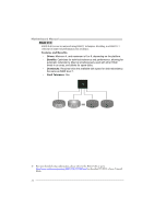
Motherboard Manual Header for Memory Voltage Overclocking: JDDRII_2.3V When processing Memory Voltage Overclocking, please place the jumper to pin1-2 Closed. The Default setting is Pin 2-3 Closed. 3 1 13 Pin 1-2 Close: Memory voltage 2.3V. 13 Pin 2-3 Close: Normal status (default). Note: 1. When "JDDRII_2.3V" jumper cap is placed on Pin 2-3, memory voltage can be manually adjusted under CMOS setup. 2. When "JDDRII_2.3V" jumper cap is placed on Pin 1-2, memory voltage will be fixed at 2.3V automatically, and can't be adjusted under COMS setup. Before setting memory voltage overclocking, please ensure that your DDR supports up to 2.3V. (Consulting your DDR supplier) On-Board LED Indicators There are 2 LED indicators on the motherboard to show system status. LED_D1 LED_D2 LED_D1 and LED_D2: These 2 LED indicate system power on diagnostics. Please refer to the table below for different messages: LED_D1 ON ON OFF OFF LED_D2 ON OFF ON OFF Message Normal Memory Error VGA Error Abnormal: CPU / Chipset error. 18
-
 1
1 -
2
-
3
-
4
-
5
-
6
-
7
-
8
-
9
-
10
-
11
-
12
-
13
-
14
-
 15
15 -
 16
16 -
 17
17 -
 18
18 -
 19
19 -
 20
20 -
 21
21 -
 22
22 -
 23
23 -
 24
24 -
 25
25 -
26
-
27
-
28
-
29
-
30
-
31
-
32
-
33
-
34
-
35
-
36
-
37
-
38
-
39
-
40
-
41
-
42
-
43
-
44
-
45
-
46
-
47
-
48
-
49
-
50
-
51
-
52
-
53
-
54
-
55
-
56
-
57
-
58
-
59
-
60
-
61
-
62
-
63
-
64
-
65
 |
 |
