Biostar TP35D2-A7 Setup Manual
Biostar TP35D2-A7 Manual
 |
View all Biostar TP35D2-A7 manuals
Add to My Manuals
Save this manual to your list of manuals |
Biostar TP35D2-A7 manual content summary:
- Biostar TP35D2-A7 | Setup Manual - Page 1
TP35D2-A7 Setup Manual FCC Information and, if not installed and used in accordance with the instructions, may cause harmful interference to radio communications. There is 's approval in writing. The content of this user's manual is subject to be changed without notice and we will not be responsible - Biostar TP35D2-A7 | Setup Manual - Page 2
13 Chapter 4: OverClock Quick Guide 20 4.1 T-Power Introduction 20 4.2 T-Power BIOS Feature 20 4.3 T-Power Windows Feature 26 Chapter 5: Useful Help 32 5.1 Driver Installation Note 32 5.2 Award BIOS Beep Code 33 5.3 Extra Information 33 5.4 Troubleshooting 35 Appendencies: SPEC In Other - Biostar TP35D2-A7 | Setup Manual - Page 3
TP35D2-A7 1.1 BEFORE YOU START Thank you for choosing our product. Before you start installing the motherboard, please make sure you follow the instructions below: „ Prepare a dry and stable working environment with sufficient lighting. „ Always disconnect the computer from power outlet - Biostar TP35D2-A7 | Setup Manual - Page 4
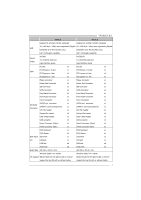
Motherboard Manual 1.3 MOTHERBOARD FEATURES Ver 5.x Ver 6.x LGA 775 LGA 775 Intel Core2Duo / Core2Quad / Celeron 4xx / Intel Core2Duo / Core2Quad / Celeron 4xx / Pentium D / Pentium 4 / Celeron D processor Pentium D / Pentium 4 / Celeron D processor CPU Supports Hyper-Threading / Execute - Biostar TP35D2-A7 | Setup Manual - Page 5
TP35D2-A7 Ver 5.x Ver 6.x USB Port x6 USB Port x6 Audio Jack x6 Audio Jack x3 Board Size 220 (W) x 305 (L) mm 220 (W) x 305 (L) mm Windows 2000 / XP / VISTA OS Support Biostar Reserves the right to add or remove support for any OS with or without notice Windows 2000 / XP / VISTA Biostar - Biostar TP35D2-A7 | Setup Manual - Page 6
Motherboard Manual 1.4 REAR PANEL CONNECTORS (FOR VER 5.X) PS/2 M ou se LA N Audio Jack PS/ 2 Ke ybo ar d COM1 USBX2 USBX2 USBX2 Center Rear Si de Line In Line Out Mic In 1.5 REAR PANEL CONNECTORS (FOR VER 6.X) PS/2 M ou se LAN PS/ 2 Ke ybo ar d COM1 USBX2 USBX2 USBX2 Line In/ Su rr - Biostar TP35D2-A7 | Setup Manual - Page 7
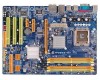
1.6 MOTHERBOARD LAYOUT JKBMS1 JPRNT1 LGA775 CPU1 TP35D2-A7 JCFAN1 JCOM1 JUSB2 DDR2_A1 DDR2_A2 DDR2_B1 DDR2_B2 JUSB1 JRJ45USB1 JATXPWR1 JAUDIO1 (for Ver 5.x) JAUDIO2 (for Ver 6.x) JATXPWR2 JNFAN1 PEX16_1 Intel P35 Super I/O PEX4_1 LAN PEX1_1 BAT1 PCI1 PCI2 CODEC PCI3 - Biostar TP35D2-A7 | Setup Manual - Page 8
Motherboard Manual CHAPTER 2: HARDWARE INSTALLATION 2.1 INSTALLING CENTRAL PROCESSING UNIT (CPU) Special Notice: Remove Pin Cap before installation, and make good preservation for future use. When the CPU is removed, cover the Pin Cap on the empty socket to ensure pin legs won't be damaged. Pin Cap - Biostar TP35D2-A7 | Setup Manual - Page 9
TP35D2-A7 Step 2: Look for the triangular cut edge on socket, and the golden dot on CPU should point forwards this triangular cut edge. The CPU will fit only in the correct orientation. Step 2-1: Step 2-2: Step 3: Hold the CPU down firmly, and then lower the lever to locked position to complete the - Biostar TP35D2-A7 | Setup Manual - Page 10
Motherboard Manual 2.2 FAN HEADERS These fan headers support cooling-fans built in the computer. The fan cable and connector may be different according to the fan manufacturer. Connect the fan cable to the connector while matching the black wire to pin#1. JCFAN1: CPU Fan Header 4 Pin Assignment 1 - Biostar TP35D2-A7 | Setup Manual - Page 11
2.3 INSTALLING SYSTEM MEMORY A. Memory Modules TP35D2-A7 DDR2_A1 DDR2_A2 DDR2_B1 DDR2_B2 1. Unlock a DIMM slot chip snap back in place and the DIMM is properly seated. B. Memory Capacity DIMM Socket Location DDR Module DDR2_A1 256MB/512MB/1GB/2GB DDR2_A2 256MB/512MB/1GB/2GB DDR2_B1 256MB - Biostar TP35D2-A7 | Setup Manual - Page 12
Motherboard Manual C. Dual Channel Memory installation To trigger the Dual Channel function of the motherboard, the memory module must meet the following requirements: Install memory module of the same density in pairs, shown in the following table. Dual Channel Status - Biostar TP35D2-A7 | Setup Manual - Page 13
TP35D2-A7 2.4 CONNECTORS AND SLOTS FDD1: Floppy Disk Connector The motherboard provides a standard floppy disk connector that supports 360K, 720K, 1.2M, 1.44M and 2.88M floppy disk types. This connector supports the provided floppy drive ribbon cables. 33 1 34 2 IDE1: Hard Disk Connector The - Biostar TP35D2-A7 | Setup Manual - Page 14
Motherboard Manual PEX16_1: PCI-Express x16 Slot - PCI-Express 1.0a compliant. - Maximum theoretical of 500MB/s totally. PEX16_1 PEX4_1 PEX1_1 PCI1~PCI3: Peripheral Component Interconnect Slots This motherboard is equipped with 3 standard PCI slots. PCI stands for Peripheral Component Interconnect, - Biostar TP35D2-A7 | Setup Manual - Page 15
TP35D2-A7 CHAPTER 3: HEADERS & JUMPERS SETUP 3.1 HOW TO SETUP JUMPERS The SETTINGS JPANEL1: Front Panel Header This 16-pin connector includes Power-on, Reset, HDD LED, Power LED, Sleep button and speaker connection. It allows user to connect the PC case's front panel switch functions. HLED - Biostar TP35D2-A7 | Setup Manual - Page 16
Motherboard Manual JATXPWR2: ATX Power Source Connector JATXPW2 allows user to connect 24-pin power connector on the ATX power supply 12V 11 +12V 12 +3.3V JATXPWR1: ATX Power Source Connector By connecting this connector, it will provide +12V to CPU power circuit. 2 1 Pin Assignment 1 +12V - Biostar TP35D2-A7 | Setup Manual - Page 17
TP35D2-A7 JUSB3/JUSB4/JUSB5: Headers for USB 2.0 Ports at Front Panel This header allows user to connect additional USB cable on the PC front panel, and also can be connected with internal USB devices, like USB user to connect the audio source from the variaty devices, like CD-ROM, DVD-ROM, PCI sound - Biostar TP35D2-A7 | Setup Manual - Page 18
pin2-3, it allows user to restore the BIOS safe setting and the CMOS data, please carefully follow the procedures to avoid damaging the motherboard. 3 1 Pin 1-2 Close: Normal Operation (default). 3 1 3 1 Pin 2-3 Close: Clear CMOS data. ※ Clear CMOS Procedures: 1. Remove AC power line. 2. Set the - Biostar TP35D2-A7 | Setup Manual - Page 19
TP35D2-A7 JSPDIF_OUT1: Digital Audio-out Connector This connector allows user to connect the PCI bracket SPDIF output header. Pin Assignment 1 +5V 2 SPDIF_OUT 3 Ground 3 1 JSPDIF_IN1: Digital Audio-in Connector (Optional) This connector allows user to connect the PCI bracket SPDIF input - Biostar TP35D2-A7 | Setup Manual - Page 20
Motherboard Manual On-Board LED Indicators There are 2 LED indicators on the motherboard to show system status. LED2 LED1 and LED2: LED1 These 2 LED indicate system power : CPU / Chipset error. On-Board Buttons There are 2 on-board buttons. RSTSW2 PWRSW1 PWRSW1: This is an on-board Power Switch - Biostar TP35D2-A7 | Setup Manual - Page 21
JPRNT1: Printer Port Connector This header allows you to connector printer on the PC. 25 TP35D2-A7 Pin Assignment 1 -Strobe 2 -ALF 3 Data 0 4 -Error 5 Data 1 6 -Init 7 Data 2 8 -Scltin 9 Data 3 10 Ground 11 Data 4 12 Ground 13 Data 5 2 1 Pin Assignment 14 Ground - Biostar TP35D2-A7 | Setup Manual - Page 22
Motherboard Manual CHAPTER 4: OVERCLOCK QUICK GUIDE 4.1 T-POWER INTRODUCTION Biostar T-Power is a whole new utility that is designed for overclock users. Based on many precise tests, Biostar Engineering Team (BET) has developed this ultimate overclock engine to raise system performance. No matter - Biostar TP35D2-A7 | Setup Manual - Page 23
TP35D2-A7 4.2 T-POWER BIOS FEATURE A. Overclocking Navigator Engine (O.N.E.): ONE provides two powerful overclocking engines: MOS and AOS for both Elite and Casual overclockers. Manual Overclock System (M.O.S.) MOS is designed for experienced overclock users. It allows users to customize personal - Biostar TP35D2-A7 | Setup Manual - Page 24
Motherboard Manual CPU Clock Ratio & CPU Clock: CPU Clock Ratio x CPU Clock = CPU Frequency. CPU Frequency is directly in proportion to system performance. To maintain the system stability, CPU voltage needs to be increased also when raising CPU frequency. PCI-E Clock Select: It helps to increase - Biostar TP35D2-A7 | Setup Manual - Page 25
TP35D2-A7 V6 Tech Engine: This setting will raise about 10%~15% of whole system performance. V8 Tech Engine: This setting will raise about 15%~25% of whole system performance. V12 Tech Engine: This setting will raise about 25%~30% of whole system performance. 23 - Biostar TP35D2-A7 | Setup Manual - Page 26
Motherboard Manual B. CMOS Reloading Program (C.R.P.): It allows users to save different CMOS settings into BIOS-ROM. Users are able to reload any saved CMOS setting for customizing system configurations. Moreover, users are able to save an ideal overclock setting during overclock operation. There - Biostar TP35D2-A7 | Setup Manual - Page 27
TP35D2-A7 C. Memory Integration Test (M.I.T.): This function is under "Overclocking Navigator Engine" item. MIT allows users to test memory compatibilities, and no extra devices or software are needed. Step 1: The default setting under this item is "Disabled"; the condition parameter should - Biostar TP35D2-A7 | Setup Manual - Page 28
Motherboard Manual D. Self Recovery System (S.R.S.): This function can't be seen under T-Power BIOS setup; and is always on whenever the system starts up. However, it can prevent system hang-up due to inappropriate overclock actions. When the system hangs up, S.R.S. will automatically log in the - Biostar TP35D2-A7 | Setup Manual - Page 29
4.3 T-POWER WINDOWS FEATURE TP35D2-A7 1. Desktop Icon After the T-Utility has been installed, a window you will see is Main Panel. Main Panel contains features as follows: a. Display the CPU Speed, CPU external clock, Memory clock, VGA clock, and PCI clock information. b. Contains About, Overclock - Biostar TP35D2-A7 | Setup Manual - Page 30
Motherboard Manual 3. Overclock/Overvoltage Panel Click the Overclock/Overvoltage button in the Main Panel, the button will be highlighted and the Overclock/Overvoltage Panel will show up as the following figure. As you can see, the Overclock Panel is on the upper side, and the Overvoltage Panel is - Biostar TP35D2-A7 | Setup Manual - Page 31
TP35D2-A7 Overclock Panel contains these features: a. "Auto-Overclock": User can click this button and T- previously verified best and stable frequency. b. "Verify": If you use the "Manual Adjust" bar to adjust the CPU frequency, then you can click this button and T-Utility will proceed a testing - Biostar TP35D2-A7 | Setup Manual - Page 32
Motherboard Manual e. "Save / Open Setting": Click Save button to save current setting to a file, and click Open button to load a previously saved setting. f. "Panel Color": Click this button to change the color of the panel. Overvoltage Panel contains these features: a. "CPU Voltage": This function - Biostar TP35D2-A7 | Setup Manual - Page 33
TP35D2-A7 5. About Panel Click the "about" button in Main Panel, the button will be highlighted and the About Panel will show up as the following figure. In this panel, you can get model name and detail information in hints of all the chipset that are related to overclocking. You can also get the - Biostar TP35D2-A7 | Setup Manual - Page 34
for better system performance. You will see the following window after you insert the CD The setup guide will auto detect your motherboard and operating system. Note: If this window didn't show up after you insert the Driver CD, please use file browser to locate and execute the file SETUP.EXE under - Biostar TP35D2-A7 | Setup Manual - Page 35
TP35D2-A7 5.2 AWARD BIOS BEEP CODE Beep Sound Meaning One long beep followed by two short Video card not found or video card beeps memory bad High-low siren sound CPU overheated System will shut down automatically One Short beep when system boot-up No error found during POST Long beeps - Biostar TP35D2-A7 | Setup Manual - Page 36
Motherboard Manual B. CPU Overheated If the system shutdown automatically after power on system for seconds, that means the CPU protection function has been activated. When the CPU is over heated, the motherboard will shutdown automatically to avoid a damage of the CPU, and the system may not power - Biostar TP35D2-A7 | Setup Manual - Page 37
TP35D2-A7 5.4 TROUBLESHOOTING Probable Solution 1. No power to the system at all 1. Make sure power cable is Power light don't illuminate, fan securely plugged in. inside power supply does not turn 2. Replace cable. on. 3. Contact technical support "CMOS Failure." Review system's equipment. - Biostar TP35D2-A7 | Setup Manual - Page 38
Motherboard Manual APPENDENCIES: SPEC IN OTHER LANGUAGE GERMAN CPU FSB Chipsatz Ver 5.x Ver 6.x LGA 775 LGA 775 Intel Core2Duo / Core2Quad / Celeron 4xx / Intel Core2Duo 1333 MHz 533 / 800 / 1066 / 1333 MHz Intel P35 Intel P35 Intel ICH9 Intel ICH9 ITE 8718F ITE 8718F Bietet die häufig - Biostar TP35D2-A7 | Setup Manual - Page 39
LAN-Anschluss x1 USB-Anschluss x6 Audioanschluss x6 Platinengröße 220 mm (B) X 305 mm (L) Windows 2000 / XP / VISTA Biostar behält sich das Recht vor, ohne OS-Unterstüt Ankündigung die Unterstützung für ein zung Betriebssystem hinzuzufügen oder zu entfernen. TP35D2-A7 Ver 6.x (Gigabit - Biostar TP35D2-A7 | Setup Manual - Page 40
Motherboard Manual FRANCE Ver 5.x Ver 6.x LGA 775 LGA 775 Processeurs Intel Core2Duo / Core2Quad 1066 / 1333 MHz Chipset Intel P35 Intel ICH9 Intel P35 Intel ICH9 ITE 8718F ITE 8718F Fournit 1066 CPU) CPU) Les DIMM à registres et DIMM avec code Les DIMM à registres et DIMM avec code - Biostar TP35D2-A7 | Setup Manual - Page 41
TP35D2-A7 Ver 5.x Ver 6.x Realtek RTL 8110SC / RTL USB x6 Port USB x6 Fiche audio x6 Fiche audio x3 Dimensions 220 mm (l) X 305 mm (H) de la carte 220 mm (l) X 305 mm (H) Windows 2000 / XP / VISTA Windows 2000 / XP /VISTA Support SE Biostar se réserve le droit d'ajouter ou de Biostar - Biostar TP35D2-A7 | Setup Manual - Page 42
Motherboard Manual ITALIAN Ver 5.x Ver 6.x LGA 775 LGA 775 Processore Intel Core2Duo / Core2Quad / Processore Intel Core2Duo / Core2Quad / Celeron 4xx / Pentium 4 / Pentium D / Celeron 4xx / Pentium 4 / Pentium D / CPU 1333 MHz Chipset Intel P35 Intel ICH9 Intel P35 Intel ICH9 ITE 8718F - Biostar TP35D2-A7 | Setup Manual - Page 43
TP35D2-A7 Ver 5.x Ver 6.x Realtek RTL 8110SC / RTL 8100C(optional) Realtek RTL 8110SC / RTL USB x6 Porta USB x6 Connettore audio x6 Connettore audio x3 Dimension 220 mm (larghezza) x 305 mm (altezza) 220 mm (larghezza) x 305 mm (altezza) i scheda Windows 2000 / XP / VISTA Sistemi Biostar - Biostar TP35D2-A7 | Setup Manual - Page 44
Motherboard Manual SPANISH Ver 5.x Ver 6.x LGA 775 LGA 775 Procesador Intel Core2Duo / Core2Quad / Procesador Intel Core2Duo / Core2Quad / Celeron 4xx / Pentium 4 / Pentium D / Celeron D Celeron 4xx / Pentium 4 / Pentium D / Celeron D CPU Conjunto de Intel P35 Intel P35 chips Intel ICH9 - Biostar TP35D2-A7 | Setup Manual - Page 45
TP35D2-A7 Ver 5.x Ver 6.x ALC888 Soporte de Soporte de sonido de Alta USB X6 Puerto USB X6 Conector de sonido X6 Conector de sonido X3 Tamaño de 220 mm. (A) X 305 Mm. (H) la placa 220 mm. (A) X 305 Mm. (H) Soporte de Windows 2000 / XP / VISTA Windows 2000 / XP / VISTA sistema Biostar - Biostar TP35D2-A7 | Setup Manual - Page 46
Motherboard Manual PORTUGUESE Ver 5.x Ver 6.x LGA 775 LGA 775 Processador Intel Core2Duo / Core2Quad / Processador Intel Core2Duo / Core2Quad / Celeron 4xx / Pentium 4 / Pentium D / Celeron D Celeron 4xx / Pentium 4 / Pentium D / Celeron D CPU Chipset Intel P35 Intel ICH9 Intel P35 Intel - Biostar TP35D2-A7 | Setup Manual - Page 47
x1 traseiro Porta USB x6 Tomada de áudio x6 Tamanho da placa 220 mm (L) X 305 mm (A) Windows 2000 / XP / VISTA Sistemas A Biostar reserva-se o direito de adicionar ou operativos remover suporte para qualquer sistema suportados operativo com ou sem aviso prévio. TP35D2-A7 Ver 6.x ALC861VD - Biostar TP35D2-A7 | Setup Manual - Page 48
Motherboard Manual POLISH Ver 5.x Ver 6.x LGA 775 LGA 775 Procesor Intel Core2Duo / Core2Quad / / 1066 / 1333 MHz Chipset Intel P35 Intel ICH9 Intel P35 Intel ICH9 Gniazda DDR2 DIMM x 4 DDR2 533 (w. FSB 533/1066 CPU) Obsługa DDR2 533 (w. FSB 533/1066 CPU) Brak obsługi Registered DIMM - Biostar TP35D2-A7 | Setup Manual - Page 49
Port LAN x1 Port USB x6 Gniazdo audio x6 Wymiary płyty 220 mm (S) X 305 mm (W) Obsluga systemu Windows 2000 / XP / VISTA Biostar zastrzega sobie prawo dodawania lub operacyjne odwoływania obsługi dowolnego systemu go operacyjnego bez powiadomienia. TP35D2-A7 Ver 6.x ALC861VD Obsługa - Biostar TP35D2-A7 | Setup Manual - Page 50
Motherboard Manual RUSSIAN Ver 5.x Ver 6.x LGA 775 LGA 775 Intel Core2Duo / Core2Quad / Intel Core2Duo / Core2Quad / CPU Celeron 4xx / Pentium 1066 / 1333 МГц 533 / 800 / 1066 / 1333 МГц Набор Intel P35 Intel P35 Intel ICH9 Intel ICH9 Слоты DDR2 DIMM x 4 Слоты DDR2 DIMM x 4 - Biostar TP35D2-A7 | Setup Manual - Page 51
TP35D2-A7 Ver 5.x Ver 6.x ALC888 High-Definition 7.1 диска ALC861VD High-Definition USB-порт x6 USB-порт x6 ода x6 x3 220 мм (Ш) X 305 мм (В) 220 мм (Ш) X 305 мм (В) Windows 2000 / XP / VISTA Biostar OS OS с Windows 2000 / XP / VISTA Biostar - Biostar TP35D2-A7 | Setup Manual - Page 52
Motherboard Manual ARABIC Ver 6.x Ver 5.x LGA 775 LGA 775 Intel Core2Duo / Core2Quad / Celeron 4xx Intel Core2Duo / Core2Quad / Celeron 4xx Pentium 4 / Pentium D / Celeron D Pentium 4 / Pentium D / Celeron D Hyper-Threading / Execute Disable Bit Hyper- - Biostar TP35D2-A7 | Setup Manual - Page 53
TP35D2-A7 Ver 6.x Ver 5.x RTL 8110SC RTL 8110SC ALC861VD Intel 5.1 ALC888 7.1 USB 6 USB 3 6 220 305 X 220 305 X Windows 2000 / XP / VISTA Windows 2000 / XP / VISTA Biostar Biostar - Biostar TP35D2-A7 | Setup Manual - Page 54
Motherboard Manual JAPANESE Ver 5.x Ver 6.x LGA 775 LGA 775 Intel Core2Duo / Core2Quad / Celeron 4xx / Intel Core2Duo / Core2Quad / Celeron 4xx / Pentium 4 / Pentium D / Celeron D processor Pentium 4 / Pentium D / Celeron D processor Hyper-Threading / Execute Disable Bit / CPU Enhanced Intel - Biostar TP35D2-A7 | Setup Manual - Page 55
x1 S/PDIF x1 S/PDIF x1 CPU x1 x2 CMOS x1 USBコネクタ x3 24ピン) x1 4ピン) x1 PS/2 x1 PS/2マウス x1 x1 LANポート x1 USBポート x6 x3 220 mm (幅) X 305 mm (高さ) Windows 2000 / XP / VISTA Windows 2000 / XP / VISTA OS Biostar OS Biostar OS 2007/05/14 53 - Biostar TP35D2-A7 | Setup Manual - Page 56
TP35D2-A7 BIOS Setup BIOS Setup 1 1 Main Menu 3 2 Standard CMOS Features 7 3 Advanced BIOS Features 9 4 Advanced Chipset Features 16 5 Integrated Peripherals 18 6 Power Management Setup 24 7 PnP/PCI Configurations 30 8 PC Health Status 32 9 OverClock Navigator 34 10 CMOS Reload Program - Biostar TP35D2-A7 | Setup Manual - Page 57
TP35D2-A7 BIOS Setup Introduction The purpose of this manual is to describe the settings in the Phoenix-Award™ BIOS Setup program on this motherboard. The Setup program allows users to modify the basic system configuration and save these settings to CMOS RAM. The power of CMOS RAM is supplied by a - Biostar TP35D2-A7 | Setup Manual - Page 58
TP35D2-A7 ACPI Support Phoenix-Award ACPI BIOS support Version 1.0b of Advanced Configuration and Power interface specification (ACPI). It provides ASL code for power management and device configuration capabilities as defined in the ACPI specification, developed by Microsoft, Intel and Toshiba. - Biostar TP35D2-A7 | Setup Manual - Page 59
TP35D2-A7 1 Main Menu Once you enter Phoenix-Award BIOS™ CMOS Setup Utility, the Main Menu will appear , the BIOS firmware is being continuously updated. The BIOS information described in this manual (Figure 1, 2, 3, 4, 5, 6, 7, 8, 9,10) is for your reference only. The actual BIOS information and - Biostar TP35D2-A7 | Setup Manual - Page 60
TP35D2-A7 Advanced BIOS Features This submenu allows you to configure advanced features of the BIOS. Advanced Chipset Features the hardware of your system. OverClock Navigator Engine (O.N.E.) ONE provides two powerful overclock engines, MOS & AOS for both overclock expertise and beginner. CMOS - Biostar TP35D2-A7 | Setup Manual - Page 61
TP35D2-A7 Load Optimized Defaults This selection allows you to reload the BIOS when problem occurs during system booting sequence. will be prompted with to enter a password. Set User Password If the Supervisor Password is not set, then the User Password will function in the same way as the Supervisor - Biostar TP35D2-A7 | Setup Manual - Page 62
TP35D2-A7 Exit Without Saving Abandon all changes made during the current session and exit setup. Confirmation message will be displayed before proceeding. Integrate Flashing Program This submenu allows you to upgrade bios. 6 - Biostar TP35D2-A7 | Setup Manual - Page 63
TP35D2-A7 2 Standard CMOS Features The items in Standard CMOS Setup Menu are divided into several categories. Each category includes no, one or more than one setup - Biostar TP35D2-A7 | Setup Manual - Page 64
TP35D2-A7 Item IDE Channel 1 Master / Slave Drive A Halt On Base Memory Extended Memory type of floppy disk drive installed in your system. Select the situation in which you want the BIOS to stop the POST process and notify you. Displays the amount of conventional memory detected during boot - Biostar TP35D2-A7 | Setup Manual - Page 65
TP35D2-A7 3 Advanced BIOS Features „ Figure 3: Advanced BIOS Setup 9 - Biostar TP35D2-A7 | Setup Manual - Page 66
CPU Feature TP35D2-A7 Delay Prior to Thermal Set this item to enable the CPU Thermal function to engage after the specified time. The Choices: 4 Min, 8 Min, 16Min (default), 32 Min. Thermal Management This option allows you to select the - Biostar TP35D2-A7 | Setup Manual - Page 67
TP35D2-A7 Limit CPUID MaxVal Set Limit CPUID MaxVal to 3, it should be "Disabled" for Windows XP. The Choices: Disabled (default), Enabled. C1E Function This item allows you to configure the Enhanced Halt State (C1E) function, which may reduce the power CPU L3 Cache Depending on the CPU/chipset - Biostar TP35D2-A7 | Setup Manual - Page 68
TP35D2-A7 Boot Seq & Floppy Setup This item allows you to setup boot sequence & Floppy. Hard Disk Boot Priority The BIOS will attempt to arrange the Hard Disk boot sequence automatically. You can change the Hard Disk booting sequence here. The Choices: Pri. Master, Pri. Slave, - Biostar TP35D2-A7 | Setup Manual - Page 69
TP35D2-A7 First/Second/Third Boot Device The BIOS will attempt to load the operating system in this order. The Choices: Floppy, LS120, Hard Disk, CDROM, ZIP100, USB-FDD, USB-ZIP, USB-CDROM, LAN, Disabled. Boot Other Device When enabled, BIOS will try to load the operating system from other device - Biostar TP35D2-A7 | Setup Manual - Page 70
TP35D2-A7 Boot Up NumLock Status Selects the NumLock State after the system switched on. The Choices: On (default) Numpad is number keys. Off Numpad is arrow - Biostar TP35D2-A7 | Setup Manual - Page 71
TP35D2-A7 APIC MODE Selecting Enabled enables APIC device mode reporting from the BIOS to the operating system. The Choices: Enabled (default), Disabled. MPS Version Control For OS The BIOS supports version 1.1 and 1.4 of the Intel multiprocessor specification. Select version supported by the - Biostar TP35D2-A7 | Setup Manual - Page 72
TP35D2-A7 4 Advanced Chipset Features This submenu allows you to configure the specific features of the chipset installed on your incorrectly. „ Figure 4: Advanced Chipset Setup System BIOS Cacheable Selecting the "Enabled" option allows caching of the system BIOS ROM at F0000h-FFFFFh, which is able - Biostar TP35D2-A7 | Setup Manual - Page 73
TP35D2-A7 Memory Hole At 15M-16M You can reserve this area of system memory for ISA adapter ROM. When this area is reserved it cannot be cached. Check the user information of peripherals that need to use this area of system memory for the memory requirements. The Choices: Disabled (default), - Biostar TP35D2-A7 | Setup Manual - Page 74
TP35D2-A7 5 Integrated Peripherals „ Figure 5. Integrated Peripherals 18 - Biostar TP35D2-A7 | Setup Manual - Page 75
TP35D2-A7 OnChip IDE Device Highlight the "Press Enter" label next to the " also called block transfer, multiple commands, or multiple sectors read / write. If your IDE hard drive supports block mode (most new drives do), select Enabled for automatic detection of the optimal number of block mode - Biostar TP35D2-A7 | Setup Manual - Page 76
in your system. As well, your operating environment requires a DMA driver (Windows 95 or OSR2may need a third party IDE bus master driver). If your hard drive and your system software both support Ultra DMA, select Auto to enable BIOS support. The Choices: Auto (default), Disabled. LEGACY Mode - Biostar TP35D2-A7 | Setup Manual - Page 77
TP35D2-A7 Onboard Serial Port 1 Select an address and corresponding interrupt for the first and second serial ports. The Choices: 3F8/IRQ4 (default), Disabled, 2F8/IRQ3, 3E8/ - Biostar TP35D2-A7 | Setup Manual - Page 78
TP35D2-A7 USB Device Setting Highlight the "Press Enter" label next to the "Onboard Device" label and press the enter key will take you a submenu with the following options: USB 1.0/2.0 Controller If your system contains a Universal Serial Bus (USB) controller, This entry is to enable/disable - Biostar TP35D2-A7 | Setup Manual - Page 79
TP35D2-A7 UFDDA/U FDDB The Choices: USB Floppy (default). No Device [Auto]: According to contents of USB MSD decide boot up type. [FDD Mode]: The USB MSD always boot up as floppy disk. [HDD Mode]: The USB MSD always boot up as hard disk. The Choices: Auto mode (default), FDD mode, HDD mode. PCIE to - Biostar TP35D2-A7 | Setup Manual - Page 80
TP35D2-A7 6 Power Management Setup The Power Management Setup Menu allows you to configure your system to utilize energy conservation and power up/power down features. „ Figure 6. Power Management Setup 24 - Biostar TP35D2-A7 | Setup Manual - Page 81
TP35D2-A7 ACPI & Wake Up Events ACPI Function This item displays the status of the Advanced Configuration and Power Management (ACPI). The Choices: Enabled (default), Disabled. ACPI Suspend Type The item allows you to select the suspend type under the ACPI operating system. The - Biostar TP35D2-A7 | Setup Manual - Page 82
TP35D2-A7 Wake-Up by PCI card When you select "Enable", a PME signal from PCI card returns the system to Full On state. The Choices: Disabled (default), Enabled. PCI Express PME The Choices: Disabled (default), Enabled. Power USB KB Wake-Up From S3 This item allows you to enable or disabled the USB - Biostar TP35D2-A7 | Setup Manual - Page 83
TP35D2-A7 PWRON After PWR-Fail This setting specifies how your system should behave after a power fail or interrupts occurs. By choosing off will leave the computer in the power off state. Choosing On will reboot the computer. Former-Sts will restore the system to the status before power failure or - Biostar TP35D2-A7 | Setup Manual - Page 84
TP35D2-A7 Power Management This category allows you to select the power saving method and is directly related to the following modes: 1. HDD Power Down. 2. Suspend Mode. There are three options of Power Management, three of which have fixed mode settings Min. Saving (default) Minimum power - Biostar TP35D2-A7 | Setup Manual - Page 85
TP35D2-A7 Suspend Type Select the Suspend Type. The Choices: Stop power button. Instant off turn off the power immediately, and Delay 4 Sec. will require you to press and hold the power button for 4 seconds to cut off the system power. The Choices: Delay 4 Sec, Instant-Off (default). HPET Support - Biostar TP35D2-A7 | Setup Manual - Page 86
(default), PCIEx. Resources Controlled By By Choosing "Auto(ESCD)" (default), the system BIOS will detect the system resources and automatically assign the relative IRQ and DMA channel for each peripheral. By Choosing "Manual", the user will need to assign IRQ & DMA for add-on cards. Be sure that - Biostar TP35D2-A7 | Setup Manual - Page 87
TP35D2-A7 . This is only configurable when "Resources Controlled By" is set to " Manual". IRQ-3 assigned to PCI Device IRQ-4 assigned to PCI Device IRQ-5 assigned default), Enabled. Assign IRQ For USB This item allows the users to choose which IRQ to assign for the USB. The Choices: Enabled (default - Biostar TP35D2-A7 | Setup Manual - Page 88
TP35D2-A7 8 PC Health Status „ Figure 8: PC Health Status Shutdown Temperature This item allows you to set up the CPU shutdown Temperature. This item is only effective under Windows 98 ACPI mode. The Choices: 70℃ / 158℉ (default) , 60℃/ 140℉,65℃/ 149℉, 75℃/ 158℉, 80℃/ 158℉, 85℃/ 158℉, 90℃/ 158℉, 95 - Biostar TP35D2-A7 | Setup Manual - Page 89
TP35D2-A7 Temperature 2 This field displays the current temperature of system. Current SYS Temp This field displays the current temperature of the system. Current CPU Temp This field displays the current temperature of CPU. Current CPU FAN Speed This field displays the current speed of CPU fan. - Biostar TP35D2-A7 | Setup Manual - Page 90
TP35D2-A7 9 OverClock Navigator „ Figure 9: Over Clock Navigator OverClock Navigator OverClock .Navigator is designed for beginners in overclock field. Based on many test and experiments from Biostar Engineer Team, OverClock Navigator provides 3 default overclock configurations that are able to - Biostar TP35D2-A7 | Setup Manual - Page 91
TP35D2-A7 Auto OverClock System The Overclock Navigator provides 3 different engines helping you to overclock your system. These every AMD CPU performs the above overclock setting ideally; the difference may vary with the installed CPU model. 2. From BET experiment, the Atholon64 FX CPU is not - Biostar TP35D2-A7 | Setup Manual - Page 92
TP35D2-A7 Manual Overclock System (M.O.S.) MOS is designed for experienced overclock users. It allows users to customize personal overclock setting. Note: Based on our test results; the overclock function achieved the best performance on AMD 3000+ CPU CPU Clock Ratio The Choices: 8X (default). Min=6 - Biostar TP35D2-A7 | Setup Manual - Page 93
TP35D2-A7 System Memory Frequency The Choices: Auto (default), 533MHz, 677MHz, 800MHz. Memory Frequency This item shows the current memory frequency. CPU Voltage This item allows you to select CPU Voltage Control. The Choices: StartUp (default); Scope: +0.012V~+0.787V. (G)MCH Voltage The Choices: 1. - Biostar TP35D2-A7 | Setup Manual - Page 94
TP35D2-A7 Integrated Memory Test Integrated Memory Test allows users to test memory module compatibilities without additional device or software. Step 1: This item is disabled on default; change it to "Enable" to precede memory test. - Biostar TP35D2-A7 | Setup Manual - Page 95
TP35D2-A7 10 CMOS Reload Program (C.R.P.) The CMOS Reload Program (CRP) allows you to save different CMOS settings into BIOS-ROM. You may reload any saved CMOS setting to change system configurations. Moreover, you may save your ideal overclock setting for easier overclocking. There are 50 sets
-
 1
1 -
 2
2 -
 3
3 -
 4
4 -
 5
5 -
 6
6 -
 7
7 -
8
-
9
-
10
-
11
-
12
-
13
-
14
-
15
-
16
-
17
-
18
-
19
-
20
-
21
-
22
-
23
-
24
-
25
-
26
-
27
-
28
-
29
-
30
-
31
-
32
-
33
-
34
-
35
-
36
-
37
-
38
-
39
-
40
-
41
-
42
-
43
-
44
-
45
-
46
-
47
-
48
-
49
-
50
-
51
-
52
-
53
-
54
-
55
-
56
-
57
-
58
-
59
-
60
-
61
-
62
-
63
-
64
-
65
-
66
-
67
-
68
-
69
-
70
-
71
-
72
-
73
-
74
-
75
-
76
-
77
-
78
-
79
-
80
-
81
-
82
-
83
-
84
-
85
-
86
-
87
-
88
-
89
-
90
-
91
-
92
-
93
-
94
-
95
 |
 |

TP35D2-A7 Setup Manual
FCC Information and Copyright
This equipment has been tested and found to comply with the limits of a Class
B digital device, pursuant to Part 15 of the FCC Rules. These limits are designed
to provide reasonable protection against harmful interference in a residential
installation. This equipment generates, uses, and can radiate radio frequency
energy and, if not installed and used in accordance with the instructions, may
cause harmful interference to radio communications. There is no guarantee
that interference will not occur in a particular installation.
The vendor makes no representations or warranties with respect to the
contents here and specially disclaims any implied warranties of merchantability
or fitness for any purpose. Further the vendor reserves the right to revise this
publication and to make changes to the contents here without obligation to
notify any party beforehand.
Duplication of this publication, in part or in whole, is not allowed without first
obtaining the vendor’s approval in writing.
The content of this user’s manual is subject to be changed without notice and
we will not be responsible for any mistakes found in this user’s manual. All the
brand and product names are trademarks of their respective companies.