Biostar TZ68A Setup Manual
Biostar TZ68A Manual
 |
View all Biostar TZ68A manuals
Add to My Manuals
Save this manual to your list of manuals |
Biostar TZ68A manual content summary:
- Biostar TZ68A | Setup Manual - Page 1
+ Setup Manual FCC Information and Copyright This equipment has been tested and found to comply with the limits of a Class B digital device, pursuant to Part 15 of the FCC Rules. These limits are designed to provide reasonable protection against harmful interference in a residential installation - Biostar TZ68A | Setup Manual - Page 2
Arrays 18 4.3 How RAID Works 18 4.4 Smart Storage Caching 22 Chapter 5: T-Series BIOS & Software 23 5.1 T-Series UEFI BIOS 23 5.2 T-Series Software 26 Chapter 6: Useful Help 36 6.1 Driver Installation Note 36 6.2 Extra Information 37 6.3 Troubleshooting 38 Appendix: SPEC In Other Languages - Biostar TZ68A | Setup Manual - Page 3
TZ68A+ 1.1 BEFORE YOU START Thank you for choosing our product. Before you start installing the motherboard, please make sure you follow the instructions Cable X 3 Rear I/O Panel for ATX Case X 1 User's Manual X 1 Fully Setup Driver CD X 1 USB 2.0 Cable X1 (optional) Serial ATA Power Cable X 1 ( - Biostar TZ68A | Setup Manual - Page 4
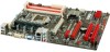
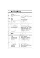
Motherboard Manual 1.3 MOTHERBOARD FEATURES SPEC CPU Chipset Socket 1155 Intel Core i7 / i5 / i3 / Pentium / Celeron processor Intel Z68 Supports Execute Disable Bit / Enhanced Intel SpeedStep® / Intel Architecture-64 / Extended Memory 64 Technology / Virtualization Technology / Hyper Threading - Biostar TZ68A | Setup Manual - Page 5
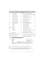
Audio-In/Out and Mic. connection Board Size 230 (W) x 305 (L) mm OS Support Windows XP / Vista / 7 Biostar reserves the right to add or remove support for any OS with or without notice 1.4 REAR PANEL CONNECTORS PS /2 Keyboard / Mouse LAN Line In/ Surround USB2.0X2 HDMI DVI-D VGA USB - Biostar TZ68A | Setup Manual - Page 6
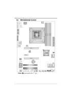
Motherboard Manual 1.5 MOTHERBOARD LAYOUT HDMI1 U SB_KBMS1 PHS PH3 PH2 PH1 VTT _LED1 ATXPW R2 C PU_FAN1 DVI1 Socket 1155 CPU1 DDR3 _A1 DDR3 _A2 DDR3 _B1 DDR3 _B2 VGA1 RJ45USB 1 AUDIO1 SY S_FA N2 PEX16_1 ATXP WR1 LAN PEX1_1 Z68 BIOS CODEC PEX16_2 SATA2 SATA1 F_AU DIO1 BAT1 J - Biostar TZ68A | Setup Manual - Page 7
CHAPTER 2: HARDWARE INSTALLATION TZ68A+ 2.1 INSTALLING CENTRAL PROCESSING UNIT (CPU) Special Notice: Remove Pin Cap before installation, and make good preservation for future use. When the CPU is removed, cover the Pin Cap on the empty socket to ensure pin legs won't - Biostar TZ68A | Setup Manual - Page 8
Motherboard Manual Step 3: Look for the triangular cut edge on socket, and the locked position to complete the installation. Step 5: Put the CPU Fan and heatsink assembly on the CPU and buckle it on the retention frame. Connect the CPU FAN power cable into the CPU_FAN1 to complete the installation. 6 - Biostar TZ68A | Setup Manual - Page 9
TZ68A+ 2.2 FAN HEADERS These fan headers support cooling-fans built in the computer. The FAN RPM rate sense 13 S Y S _FA N1 Note: The SYS_FAN1/SYS_FAN2 support 3-pin head connectors; the CPU_FAN1 supports 4-pin head connector. When connecting with wires onto connectors, please note that the red - Biostar TZ68A | Setup Manual - Page 10
DDR3_A1 DDR3_A2 DDR3_B1 DDR3_B2 Motherboard Manual 2.3 INSTALLING SYSTEM MEMORY A. Memory Modules 1. Unlock a DIMM slot by pressing the retaining clips outward. Align a DIMM on the slot such that the notch on the DIMM - Biostar TZ68A | Setup Manual - Page 11
TZ68A+ B. Memory Capacity DIMM Socket Location DDR3 Module DDR3_A1 512MB/1GB/2GB/4GB/8GB DDR3_A2 512MB/1GB/2GB/4GB/8GB DDR3_B1 512MB/1GB/2GB/4GB/8GB DDR3_B2 512MB/1GB/2GB/4GB/8GB Total Memory Size Max is 32GB. C. Dual Channel Memory Installation installed, X means memory not installed.) - Biostar TZ68A | Setup Manual - Page 12
Motherboard Manual 2.4 CONNECTORS AND SLOTS SATA1/SATA2: Serial ATA3 Connectors The motherboard has a PCI to SATA Controller with 2 channels SATA3 interface, it satisfies the SATA 3.0 spec and with transfer rate of 6.0Gb/s. SATA2 SATA1 7 4 1 Pin Assignment 1 Ground 2 TX+ 3 TX4 Ground 5 RX6 RX+ 7 - Biostar TZ68A | Setup Manual - Page 13
TZ68A+ ATXPWR1: ATX Power Source Connector This connector allows user to connect 24-pin power connector on the ATX power supply. 12 24 1 13 Pin Assignment - Biostar TZ68A | Setup Manual - Page 14
Motherboard Manual PEX16_1: PCI-Express Gen2 x16 Slot - PCI-Express 2.0 compliant. - Maximum theoretical realized bandwidth of 8GB/s simultaneously per direction, for an aggregate of 16GB/s totally. - PCI-Express Gen2 supports a raw bit-rate of 5.0Gb/s on the data pins. - 2X bandwidth over the PCI- - Biostar TZ68A | Setup Manual - Page 15
TZ68A+ CHAPTER 3: HEADERS & JUMPERS SETUP 3.1 HOW TO SETUP JUMPERS The illustration shows how to set up jumpers. When the jumper cap is placed on pins, the jumper is "close", if not, that means the jumper is "open". Pin opened Pin closed Pin1-2 closed 3.2 DETAIL SETTINGS 12 Hard drive 13 LED - Biostar TZ68A | Setup Manual - Page 16
Motherboard Manual F_AUDIO1: Front Panel Audio Header This header allows user to connect the front audio output cable with the PC front 8 Key 9 Left line in 10 Jack Sense 1 9 JSPDIFOUT1: Digital Audio-out Connector This connector allows user to connect the PCI bracket SPDIF output header - Biostar TZ68A | Setup Manual - Page 17
TZ68A+ JCMOS1: Clear CMOS Header Placing the jumper on pin2-3 allows user to restore the BIOS safe setting and the CMOS data. Please carefully follow the procedures to avoid damaging the motherboard. 13 Pin 1-2 Close: Normal Operation (default). 13 13 Pin 2-3 Close: Clear CMOS data. ※ Clear CMOS - Biostar TZ68A | Setup Manual - Page 18
Motherboard Manual J_PRINT1: Printer Port Connector This header allows you to connector printer on the PC. 2 1 Pin Assignment 1 - Ground 23 PE 24 Ground 25 SCLT 26 Key J_COM1: Serial Port Connector The motherboard has a Serial Port Connector for connecting RS-232 Port. 2 10 1 9 - Biostar TZ68A | Setup Manual - Page 19
TZ68A+ On-Board LED Indicators There are 7 LED indicators on the motherboard showing system status. PHS PH3 PH2 PH1 VT T _LE D1 LED _D2 LED _D1 LED_D1 & LED_D2: Debug Indicators PHS / PH1 ~ PH3 / VTT_LED1: Power Status Indicators - Biostar TZ68A | Setup Manual - Page 20
Motherboard Manual CHAPTER 4: RAID FUNCTIONS 4.1 OPERATING SYSTEM Supports Windows Vista and Windows 7. 4.2 RAID ARRAYS RAID supports the following types of RAID arrays: RAID 0: RAID 0 defines a disk striping scheme that improves disk read and write times for many applications. RAID 1: RAID 1 - Biostar TZ68A | Setup Manual - Page 21
the data can reside on the same disk or on a second redundant drive in the array. RAID 1 provides a hot-standby copy of data if the active volume or drive is corrupted or becomes unavailable because of a hardware failure. RAID techniques can be applied for high-availability solutions, or as a form - Biostar TZ68A | Setup Manual - Page 22
Motherboard Manual RAID 10: RAID 1 drives can be stripped using RAID 0 techniques. Resulting in a RAID 10 solution for improved resiliency, performance and rebuild performance. Features and Benefits Drives: Minimum 4, and maximum is 6 or 8, depending on the platform. Benefits: Optimizes for both - Biostar TZ68A | Setup Manual - Page 23
TZ68A+ RAID 5: RAID 5 stripes both data and parity information across three or more drives. It writes data and parity blocks across all the drives in the array. Fault tolerance is maintained by ensuring that the parity information for any given block of data is placed on a different drive from those - Biostar TZ68A | Setup Manual - Page 24
1. Install RAID drives (RAID 0, 1, 5) and an Intel SSD. 2. Activate RAID mode from BIOS, and install operating system. 3. Insert the Setup CD to the optical drive, and Install all drivers (including Intel(R) Rapid Storage Technology Driver). After all processes finish, reboot the system. 4. Intel - Biostar TZ68A | Setup Manual - Page 25
: Update UEFI BIOS file from USB Flash Drive TZ68A+ !! WARNING !! For better system performance, the UEFI BIOS firmware is being continuously updated. The UEFI BIOS information described below in this manual is for your reference only and the actual UEFI BIOS information and settings on board may - Biostar TZ68A | Setup Manual - Page 26
CPU/System from overheat problem and maintain the system temperature at a safe level. Main BIOS SETUP UTILITY Advanced Chipset Boot Security O.N.E Save & Exit > PCI Subsystem Settings > ACPI Settings/WakeUp Event control > CPU Configuration > SATA Configuration > USB Configuration > SMART FAN - Biostar TZ68A | Setup Manual - Page 27
TZ68A+ Advanced SMART FAN Control CPU Smart FAN > CPU FAN Calibrate Control Mode FAN Ctrl OFF(oC) FAN Ctrl ON(oC) FAN Ctrl Start value FAN Ctrl Sensitive BIOS SETUP UTILITY [Disabled] [Manual with an interval of 1. Fan Ctrl Start Value This item sets CPU FAN Start Speed Value. The range is from 0~ - Biostar TZ68A | Setup Manual - Page 28
Motherboard Manual 5.2 T-SERIES SOFTWARE Installing T-Series Software 1. Insert the Setup CD to the optical drive. The driver installation program would appear if the Auto-run function has been enabled. 2. Select Software Installation overclocking profiles saving unlimitedly, and pre-set OC modes are - Biostar TZ68A | Setup Manual - Page 29
TZ68A+ The CPU tab provides information on the CPU and motherboard. The Memory tab provides information on the memory module(s). You can select memory module on a specific slot to see its information. The OC Tweaker tab allows you to change system clock settings and voltages settings. It also - Biostar TZ68A | Setup Manual - Page 30
Motherboard Manual 3 Pre-set Modes: V6, V12, AUTO for different overclocking experience. The HW Monitor tab allows you to monitor hardware voltage, fan speed, and temperature. Besides, you also can set related values for CPU Smart Fan. 28 - Biostar TZ68A | Setup Manual - Page 31
TZ68A+ Pressing TOVERCLOCKER logo displays information about manufacturer and software version. You can update current version by clicking the button "Live Update." Green Power II Utility BIOSTAR G.P.U II (Green Power Utility) is a new function. The utility enhances energy efficiency by disabling - Biostar TZ68A | Setup Manual - Page 32
Motherboard Manual G.P.U Mode Setting This utility provides five modes, upon your requirements, to improve system performance or to save power consumption. Note: Even if the modes saving more power - Biostar TZ68A | Setup Manual - Page 33
you may have encountered, and then send these information to our tech-support department to help you fix the problem. Before you use this utility,please set Outlook Express as your default e-mail clientapplication program. * represent s import ant information that you must provide. Without this - Biostar TZ68A | Setup Manual - Page 34
your system information including motherboard/BIOS/CPU/video/ device/OS information. This information is also concluded in the sent mail. We will not share customer's data with any other third parties, so please feel free to provide your system information while using eHot-Line service. If you are - Biostar TZ68A | Setup Manual - Page 35
TZ68A+ BIOS Update BIOS Update is a convenient utility which allows you to update your motherboard BIOS under Windows system. Show current BIOS information Update BIOS from the Internet Update BIOS with a BIOS file Once click on this button, the saving dialog will show. Choose the - Biostar TZ68A | Setup Manual - Page 36
the system boots up and the full screen logo shows, press key to enter BIOS setup. In the BIOS setup, use the Load Optimized Defaults function and then Save and Exit Setup to exit BIOS setup. BIOS Update is completed. All the information and content above about the T-Series software are - Biostar TZ68A | Setup Manual - Page 37
or BMP as your boot logo so as to customize your computer. Please follow the following instructions to update boo logo: 1. Load Image:Choose the picture as the boot logo. 2. Transform:Transform the picture for BIOS and preview the result. 3. Update Bios:Write the picture to BIOS Memory to complete - Biostar TZ68A | Setup Manual - Page 38
window didn't show up after you insert the Driver CD, please use file browser to locate and execute the file SETUP.EXE under your optical drive. A. Driver Installation To install the driver, please click on the Driver icon. The setup guide will list the compatible driver for your motherboard and - Biostar TZ68A | Setup Manual - Page 39
TZ68A+ 6.2 EXTRA INFORMATION CPU Overheated If the system shutdown automatically after power on system for seconds, that means the CPU protection function has been activated. When the CPU is over heated, the motherboard and boot up the system. Or you can: 1. Clear the CMOS data. (See "Close CMOS - Biostar TZ68A | Setup Manual - Page 40
"Invalid Configuration" or "CMOS Failure." Review system's equipment. Make sure correct information is in setup. System cannot boot after user installs a 1. second hard drive. 2. Set master/slave jumpers correctly. Run SETUP program and select correct drive types. Call the drive manufacturers for - Biostar TZ68A | Setup Manual - Page 41
TZ68A+ This page is intentionally left blank. 39 - Biostar TZ68A | Setup Manual - Page 42
Motherboard Manual APPENDIX: SPEC IN OTHER LANGUAGES GERMAN Spezifikationen Unterstützt Execute Disable Bit / Enhanced Intel Socket 1155 SpeedStep® / Intel Architecture-64 / Extended CPU Intel Core i7 / i5 / i3 / Pentium / Celeron Memory 64 Technology / Virtualization Technology / - Biostar TZ68A | Setup Manual - Page 43
CMOS löschen"-Sockel USB2.0-Anschluss Verbraucher-IR Anschluss Druckeranschluss Anschluss Serieller Anschluss S/PDIF Ausgangsanschluss Stromanschluss (24-polig) Stromanschluss (8-polig) TZ68A HDMI- Z68) x3 Platinengröße 230 mm (B) X 305 mm (L) OS-Unterstüt zung Windows XP / Vista / 7 Biostar - Biostar TZ68A | Setup Manual - Page 44
FRENCH SPEC Prend en charge les technologies d'exécution de bit Socket 1155 de désactivation / Intel SpeedStep® optimisée/ UC Processeurs Intel Core i7 / i5 / i3 / Pentium / d'architecture Intel 64 / de mémoire étendue 64 / de Celeron virtualisation / Hyper Threading Chipset Intel Z68 - Biostar TZ68A | Setup Manual - Page 45
Prend en charge la fonction de sortie audio x1 numérique x1 x1 x1 x1 x1 x1 x1 x2 x2 USB3.0 dispositifs (par ASM1042) USB2.0/USB1.X dispositifs (par Z68) x3 Dimensions 230 mm (l) X 305 mm (H) de la carte Support SE Windows XP / Vista / 7 Biostar se réserve le droit d'ajouter ou de - Biostar TZ68A | Setup Manual - Page 46
Motherboard Manual ITALIAN SPECIFICA CPU Socket 1155 Processore Intel Core i7 / i5 / i3 / Pentium / Celeron Chipset Intel Z68 Supporto di Execute Disable Bit / Enhanced Intel SpeedStep® / Architettura Intel 64 / Tecnologia Extended Memory 64 / Tecnologia Virtualization / Hyper Threading IT8728 - Biostar TZ68A | Setup Manual - Page 47
d'output audio digitale Connettore alimentazione x1 (24 pin) Connettore alimentazione x1 (8 pin) Tastiera / Mouse PS/2 x1 Porta HDMI x1 da Z68) Connettore audio x3 Dimension 230 mm (larghezza) x 305 mm i scheda (altezza) Sistemi operativi Windows XP / Vista / 7 supportati Biostar si - Biostar TZ68A | Setup Manual - Page 48
Motherboard Manual SPANISH Especificación Admite Bit de deshabilitación de ejecución / Intel Socket 1155 SpeedStep® Mejorado / Intel Architecture-64 / CPU Procesador Intel Core i7 / i5 / i3 / Pentium / Tecnología Extended Memory 64 / Tecnología de Celeron virtualización / Hyper Threading - Biostar TZ68A | Setup Manual - Page 49
TZ68A Cabecera de borrado de CMOS X1 Conectores Conector de impresora Puerto serie X1 Conector de Ratón PS/2 X1 Ratón HDMI X1 Puerto VGA X1 Panel Puerto Z68) Conector de sonido X3 Tamaño de 230 mm. (A) X 305 Mm. (H) la placa Soporte de sistema Windows XP / Vista / 7 operativo Biostar - Biostar TZ68A | Setup Manual - Page 50
Motherboard Manual PORTUGUESE ESPECIFICAÇÕES Suporta as tecnologias Execute Disable Bit / Socket 1155 Enhanced IntelSpeedStep® / Intel Arquitecture -64 CPU Processador Intel Core i7 / i5 / i3 / Pentium / / Extended Memory 64 / Virtualization / Hyper Celeron Threading Chipset Intel Z68 - Biostar TZ68A | Setup Manual - Page 51
TZ68A Conector para limpeza do CMOS x1 Conector USB2.0 pinos) Teclado / Rato PS/2 x1 Porta HDMI x1 Entradas/S aídas no painel traseiro Porta Z68) Tomada de áudio x3 Tamanho da placa 230 mm (L) X 305 mm (A) Sistemas A Biostar reserva-se o direito de adicionar ou operativos Windows - Biostar TZ68A | Setup Manual - Page 52
Motherboard Manual POLISH SPEC Procesor Socket 1155 Procesor Intel Core i7 / i5 / i3 / Pentium / Celeron Obsługa Execute Disable Bit / Enhanced Intel SpeedStep® / Intel Architecture-64 / Extended Memory 64 Technology / Virtualization Technology / Hyper Threading Chipset Intel Z68 Gniazda DDR3 - Biostar TZ68A | Setup Manual - Page 53
Port HDMI x1 Port VGA x1 Port DVI-D x1 Back Panel Port LAN x1 I/O Port USB2.0 x2 Port USB3.0 Gniazdo audio x2 USB3.0 urządzeń (przez ASM1042) USB2.0/USB1.X urządzeń (przez Z68) x3 Wymiary płyty 230 mm (S) X 305 mm (W) Obsluga systemu Windows XP / Vista / 7 operacyjne go Biostar - Biostar TZ68A | Setup Manual - Page 54
Motherboard Manual RUSSIAN СПЕЦ CPU Execute Disable Bit / Socket 1155 Enhanced Intel SpeedStep® / Intel Architecture-64 Intel Core i7 / i5 / i3 / Pentium / ый / Extended Memory 64 Technology Celeron Hyper Threading Набор Intel Z68 Слоты DDR3 DIMM x 4 16 ГБ память - Biostar TZ68A | Setup Manual - Page 55
x1 S/PDIF x1 24 вывод) x1 8 вывод) x1 PS/2 x1 Порт HDMI x1 Задняя Порт VGA Порт DVI-D Порт LAN USB2.0-порт USB3.0-порт ода x1 x1 x1 x2 x2 USB3.0 ASM1042) USB2.0/USB1.X Z68) x3 230 мм (Ш) X 305 мм (В) Windows XP / Vista / 7 OS Biostar OS 53 - Biostar TZ68A | Setup Manual - Page 56
Motherboard Manual ARABIC Execute Disable Bit / Enhanced Intel SpeedStep® / Intel Architecture-64 / Extended Memory 64 Technology / Virtualization Technology / Hyper Threading Socket 1155 Intel Core i7 / i5 / i3 / Pentium Celeron Intel Z68 DDR3 4 - Biostar TZ68A | Setup Manual - Page 57
1 Smart Fan 2 1 3 USB2.0 1 CMOS USB2.0 1 1 1 S/PDIF 1 24 1 8 1 PS/2 1 1 1 1 2 USB3.0 2 ASM1042 USB2.0/USB1.X Z68 3 HDMI VGA DVI-D USB2.0 USB3.0 230 305 X Biostar Windows XP / Vista - Biostar TZ68A | Setup Manual - Page 58
Motherboard Manual JAPANESE 仕様 Execute Disable Bit / Enhanced Intel SpeedStep® / Socket 1155 Intel Architecture-64 / Extended Memory 64 CPU Intel Core i7 / i5 / i3 / Pentium / Celeron プロ Technology / Virtualization Technology / Hyper セッサ Threading Intel Z68 DDR3 DIMM x 4 DDR3 - Biostar TZ68A | Setup Manual - Page 59
230 mm (幅) X 305 mm (高さ) OS Windows XP / Vista / 7 TZ68A+ 仕様 x2 1つのSATA3 x4 1つのSATA2 x1 x1 x1 CPU x2 x1 2 USB2.0 x3 x1 x1 1 x1 x1 x1 x1 x1 x1 x1 x1 x1 x2 x2 USB3.0 ASM1042) USB2.0/USB1.X Z68) x3 Biostar OS 2011/04/20 57
-
 1
1 -
 2
2 -
 3
3 -
 4
4 -
 5
5 -
 6
6 -
 7
7 -
8
-
9
-
10
-
11
-
12
-
13
-
14
-
15
-
16
-
17
-
18
-
19
-
20
-
21
-
22
-
23
-
24
-
25
-
26
-
27
-
28
-
29
-
30
-
31
-
32
-
33
-
34
-
35
-
36
-
37
-
38
-
39
-
40
-
41
-
42
-
43
-
44
-
45
-
46
-
47
-
48
-
49
-
50
-
51
-
52
-
53
-
54
-
55
-
56
-
57
-
58
-
59
 |
 |
TZ68A+ Setup Manual
FCC Information and Copyright
This equipment has been tested and found to comply with the limits of a Class
B digital device, pursuant to Part 15 of the FCC Rules. These limits are designed
to provide reasonable protection against harmful interference in a residential
installation. This equipment generates, uses, and can radiate radio frequency
energy and, if not installed and used in accordance with the instructions, may
cause harmful interference to radio communications. There is no guarantee
that interference will not occur in a particular installation.
The vendor makes no representations or warranties with respect to the
contents here and specially disclaims any implied warranties of merchantability
or fitness for any purpose. Further the vendor reserves the right to revise this
publication and to make changes to the contents here without obligation to
notify any party beforehand.
Duplication of this publication, in part or in whole, is not allowed without first
obtaining the vendor’s approval in writing.
The content of this user’s manual is subject to be changed without notice and
we will not be responsible for any mistakes found in this user’s manual. All the
brand and product names are trademarks of their respective companies.
Dichiarazione di conformità
sintetica
Ai sensi dell’art. 2 comma 3 del D.M.
275 del 30/10/2002
Si dichiara che questo prodotto è
conforme alle normative vigenti e
soddisfa i requisiti essenziali richiesti
dalle direttive
2004/108/CE, 2006/95/CE e
1999/05/CE
quando ad esso applicabili
Short Declaration of conformity
We declare this product is complying
with the laws in force and
meeting all
the essential requirements as specified
by the directives
2004/108/CE, 2006/95/CE and
1999/05/CE
whenever these laws may be applied