Black & Decker CM1936 Type 1 Manual - CM1936 - Page 6
Preparation - blade
 |
View all Black & Decker CM1936 manuals
Add to My Manuals
Save this manual to your list of manuals |
Page 6 highlights
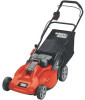
PREPARATION PLEASE REFER TO DIAGRAMS (A, B, C...) AND ITEM NUMBERS (1, 2, 3...) AS NOTED THROUGHOUT MANUAL. FOR EXAMPLE, A-1 REFERS TO ITEM 1 IN FIGURE A. UNPACKING - (FIGURES A, A1, A2) STEP 1: Raise the handle section A-1 into place and secure by tightening the two lower knobs A-2. Be careful not to pinch power cord. CAUTION: Pinch point. To avoid being pinched, keep fingers away from area between handles when raising. A A1 STEP 2: Carefully cut down the and fold the flap down sides of the as shown. boWx AonRtNheINopGp:osSitehaernpdbolaf dthee. handle Keep body parts away from blade. STEP 3: With the carton end cut open, remove the cardboard filler, charger, accessory bag and grass bag and push the mower out of the opened carton. A2 HANDLE ADJUSTMENT - (FIGURE B) Your mower has a variable height handle adjustment feature. To adjust the handle position to suit your height preference, use the following procedure: 1. Remove both hex nuts and flat washer B-1 on the middle part of the handlebars using a 1/2 inch wrench. Remove the carriage bolts B-2. 2. Slide the upper handle into one of the 3 adjustment positions B-3, aligning the holes in the upper and lower handles. 3. Insert carriage bolts and install the flat washers and hex nuts, tighten securely. B 6
-
 1
1 -
 2
2 -
 3
3 -
 4
4 -
 5
5 -
 6
6 -
 7
7 -
 8
8 -
 9
9 -
 10
10 -
 11
11 -
 12
12 -
13
-
14
-
15
-
16
-
17
-
18
-
19
-
20
-
21
-
22
-
23
-
24
-
25
-
26
-
27
-
28
-
29
-
30
-
31
-
32
-
33
-
34
-
35
-
36
-
37
-
38
-
39
-
40
-
41
-
42
-
43
-
44
-
45
-
46
-
47
 |
 |
