Bosch 1-9/16 Parts List - Page 2
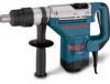
Rotary, Hammer
 |
View all Bosch 1-9/16 manuals
Add to My Manuals
Save this manual to your list of manuals |
Page 2 highlights
11247 ROTARY HAMMER Pos. Part Number Description {Qty.} 1 2 4 5 6 7 9 13 14 15 20 21 22 24 25 27 28 34 38 42 43 44 47 48 51 53 57 69 72 74 75 79 81 84 85 86 87 94 95 97 99 * 102 * 102 104 111 112 113 116 117 1 615 102 154 1 614 220 150 1 617 200 091 1 614 461 034 1 610 703 053 1 601 302 018 1 611 110 C59 1 610 900 026 1 610 905 028 1 616 610 085 1 618 597 079 1 610 508 044 1 610 591 033 1 610 500 020 1 613 100 029 1 600 591 032 1 614 621 000 1 610 516 013 1 615 190 098 1 614 336 041 1 615 500 303 1 614 617 003 1 610 300 064 1 616 334 012 1 616 333 041 1 610 290 068 1 618 710 081 1 610 099 004 1 616 317 064 1 611 921 001 1 615 132 078 1 613 435 015 1 615 132 079 1 612 025 050 1 618 040 074 1 613 490 002 1 611 316 019 1 610 102 056 1 610 210 173 1 610 031 005 1 610 102 059 1 610 102 057 1 610 102 058 1 610 210 160 1 610 290 064 1 613 300 008 1 613 435 009 1 610 311 017 1 610 913 004 Motor Housing Field Switch w/pos. 818 Cord Strain Releif Cord Clamp Label Ball Bearing Ball Bearing Fan Tool Holder Dust Shield Sleeve Disc Lock Bolt Air Deflector Spring Flange Cover Bush Holder w/pos. 811, 817 Cover Spring Sleeve Sleeve Gear Washer Striker Bracket Eccentric Gear Plate Handle Screw {2} Handle Cover Auxiliary Handle Clamp Holder T-Bolt Clamping Band Washer {2} O-Ring Washer Washer Shim 0.3mm Shim 0.2mm O-Ring Bushing Nut Screw {2} Bushing Needle Bearing {2} Service Notes: F/C Pos. Part Number Description {Qty.} F/C 71 121 1 610 328 019 Bushing 82 22 124 1 610 115 001 Sleeve 82 15 126 2 910 211 019 Screw 89 131 1 611 110 C55 Label 9 11 134 2 910 110 116 Screw 89 11 135 1 614 414 016 Cable 10 89 137 2 916 699 130 Lock Washer 65 9 138 1 611 015 053 Gasket 79 60 141 1 610 290 066 Seal 77 61 142 1 610 290 069 Seal 77 23 143 2 916 540 017 Spring Ring 89 84 145 1 610 119 012 Retaining Ring 89 92 153 2 916 540 020 Retaining Ring 89 86 154 2 916 660 023 Retaining Ring 89 86 160 1 610 210 161 Ring 9 86 162 1 610 210 163 O-Ring 78 24 165 1 610 210 079 O-Ring 78 86 166 1 613 200 015 Pin 66 9 167 1 610 283 033 Seal 77 9 171 1 613 435 016 Screw {6} 89 25 172 1 613 435 013 Screw {4} 89 174 1 613 435 012 Screw {4} 89 70 175 2 912 401 018 Screw {2} 89 27 176 1 613 435 012 Screw {2} 89 82 177 1 603 435 051 Screw {2} 89 82 178 1 604 412 069 Cable 10 33 803 1 614 011 090 Armature Assembly AW 65 w/pos. 13, 14, 15, 95, 44 111, 112, 141, 145 62 808 1 611 104 999 Nameplate 9 34 811 1 617 014 138 Brush Set 26 9 817 1 614 652 004 Brush Spring {2} 27 74 818 2 910 011 088 Screw {2} 89 89 821 1 617 000 842 Bushing Assembly 82 74 w/pos. 121, 142, 167 9 835 1 617 000 448 Guide Tube Assembly 43 80 840 1 617 000 847 Gear Housing Assembly 72 80 w/pos. 95, 104, 141, 145 80 849 1 617 000 839 Fork Assembly 62 65 856 1 617 000 843 Piston Assembly 47 78 w/pos. 165 65 860 1 617 000 844 Clutch Assembly 67 65 873 1 617 000 860 Gear Housing Cover 70 65 w/pos. 138 65 884 1 612 025 055 Auxiliary Handle 9 78 w/pos. 84, 85, 86, 87 82 895 1 615 430 019 Oil 1 89 897 1 617 000 446 Service Pack 78 89 w/pos. 21, 138, 143, 162 82 165, 811 56 898 1 615 437 511 Oil w/pos. 138 1 + = Not Illustrated * = As Required F/C = Failure Code AW = Refer to AW Labor Time Chart
-
 1
1 -
 2
2
 |
 |
