Bosch 11221DVS Operating Instructions - Page 7
Operating Instructions - rotary hammer
 |
UPC - 000346276848
View all Bosch 11221DVS manuals
Add to My Manuals
Save this manual to your list of manuals |
Page 7 highlights
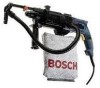
BM 1619929265 2/03 2/11/03 4:09 PM Page 7 Operating Instructions VARIABLE SPEED CONTROLLED TRIGGER SWITCH Your tool is equipped with a variable speed trigger switch. The tool speed can be controlled from the minimum to maximum nameplate RPM by the pressure you apply to the trigger. Apply more pressure to increase the speed and release pressure to decrease speed. USING THE VACUUM ASSEMBLY Mount the vacuum assembly to the tool by loosening the wing knob in the auxiliary handle then insert the hex rod into the hex hole in the auxiliary handle and secure with the wing knob. Insert the desired diameter SDS bit through the fixture and vacuum sealing cap into the dust shield on the front of the SDS tool holder. DEPTH GAUGE Set the depth gauge by loosening the wing knob and compressing the vacuum assembly bracket towards the tool. When the desired length of bit is exposed, slide the depth gauge stop up against the vacuum assembly bracket and retighten the knob. The bracket is spring loaded and will return to the extended position. (When drilling, it will compress until the depth gauge stop is engaged.) Make sure the hose is connected between the vacuum bracket assembly and the vacuum hose connection . Next, mount the bag to the tool by means of the bayonet style fitting on the dust bag connection mount and rotate the bag 90° to lock it in place. (Note: The dust bag should be emptied frequently by sliding the plastic sealing bar off of the bottom. This will insure optimum performance.) If the dust extraction feature is not being used, place the plug into the vacuum hose connection hole. INSTALLING ACCESSORIES Clean the insert shank end of the accessory to remove any debris, then lightly grease with a light oil or lubricant. Insert accessory into the tool holder through the dust shield, while twisting and pushing inward until it locks automatically into place. Pull outward on the acessory to be certain it is locked into the tool holder (fig. 2). NOTE: The high efficiency available from the rotary hammers can only be obtained if sharp and undamaged accessories are used. The "cost" to maintain sharp and undamaged accessories is more than offset by the "time saved" in operating the tool with sharp accessories. REMOVING ACCESSORIES ! WARNING Accessories may be hot after use. Avoid contact with skin and use proper protective gloves or cloth to remove. To remove an accessory, pull and hold locking sleeve backward and pull bit forward. All accessories should be wiped clean after removing. FIG. 2 DUST SHIELD LOCKING SLEEVE SDS BIT (NOT INCLUDED -7-
-
 1
1 -
 2
2 -
 3
3 -
 4
4 -
 5
5 -
 6
6 -
 7
7 -
 8
8 -
 9
9 -
 10
10 -
 11
11 -
 12
12 -
13
-
14
-
15
-
16
-
17
-
18
-
19
-
20
-
21
-
22
-
23
-
24
-
25
-
26
-
27
-
28
 |
 |
