Bosch 1347A Parts List - Page 2
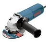
Grinder - parts
 |
UPC - 000346017571
View all Bosch 1347A manuals
Add to My Manuals
Save this manual to your list of manuals |
Page 2 highlights
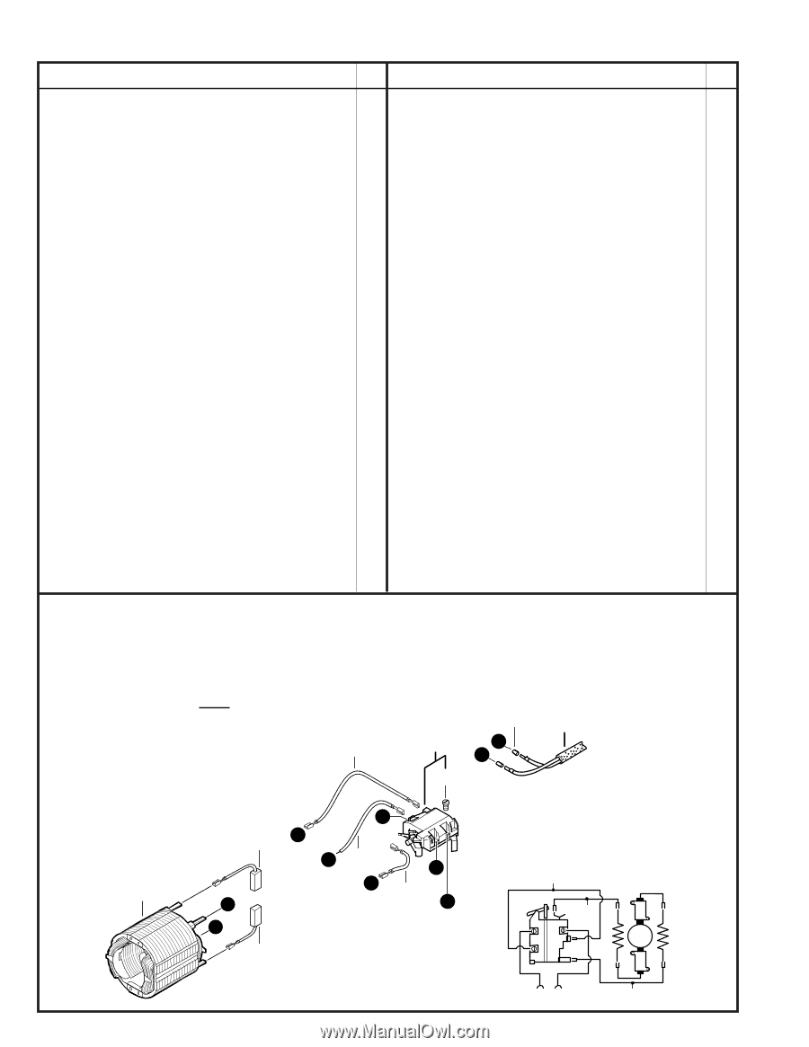
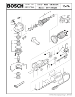
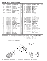
1347A 4-1/2" MINI GRINDER Pos. Part Number Description {Qty.} F/C Pos. Part Number Description {Qty.} F/C 1 2 3 3/5 4 4/1 5/1 6 7 9 13 14 17 18 20 22 23 + 23.1 25 26 27 29 31 32 33 * 35 * 35.1 * 35.2 36 1 605 108 151 1 604 220 226 1 604 010 261 1 606 610 121 1 607 200 086 2 910 091 047 1 900 452 012 2 600 703 013 1 601 302 017 2 610 906 844 2 610 994 435 3 600 900 512 1 604 652 014 1 604 611 026 2 610 906 860 1 602 319 002 1 602 026 057 1 602 026 050 1 600 508 010 1 600 502 020 1 600 206 025 1 601 328 005 2 916 660 013 3 603 523 503 1 600 210 035 1 600 136 012 1 600 136 010 1 600 136 011 1 600 150 011 Motor Housing 71 Field 120V 22 Armature w/Fan 120V AW w/pos. 3/5, 13 Fan 23 Switch On/Off 120V 15 w/pos. 4/1 Screw {2} 89 Terminal Sleeve {2} 11 Strain Relief 11 Cord Clamp 89 Label "1347A" 9 Ball Bearing 60 Ball Bearing 61 Brush Spring {2} 27 Switch Spring 27 Label "Caution" 9 Switch Slide 64 Switch Button 9 Switch Button (Deadman) 9 Housing Cover 70 Rubber Bearing Sleeve 82 Rubber Bearing Sleeve 82 Air Deflector 24 Retaining Ring 89 Spindle 5/8"-11 52 O-Ring 78 Shim 0.1mm 65 Shim 0.2mm 65 Shim 0.3mm 65 Spring Washer 65 38 1 606 333 606 40 2 916 660 009 41 2 610 910 319 42 2 610 904 744 43 1 606 333 605 45 1 603 300 016 47 2 910 611 018 48 2 910 611 405 49 3 603 429 515 53 1 604 448 005 54 1 604 448 006 55 2 910 611 021 67 1 601 110 358 104 1 601 008 003 650/2 2 610 992 248 650/3 2 610 910 341 653 1 602 025 027 750/4 1 607 950 043 752 2 610 906 260 752/4 2 910 022 197 805 3 604 460 555 808 3 601 119 595 810 1 607 014 116 813 1 607 000 253 816 2 601 323 021 821 1 605 806 480 828 1 607 000 936 Crown Gear 32 Retaining Ring 89 Bushing 56 Ball Bearing 51 Bevel Gear 33 Nut 89 Screw 89 Screw {4} 89 Screw {4} 89 Cable 95mm 10 Cable 40mm 10 Screw {5} 89 Label "Caution" 9 Insulating Plate {2} 9 Inner Flange 5/8"-11 91 Outer Flange 5/8"-11 91 Auxiliary Handle 9 Spanner Wrench 9 Guard 4-1/2" 92 w/pos. 652/4 Screw 89 Cord 120V 18/2 11 Nameplate 9 Brush Set 120V 26 Spindle Lock Assembly 81 Brush Holder {2} 25 Gear Housing Assembly 72 w/pos. 813 Gear Cover Assembly 70 w/pos. 31, 33, 42 Service Notes: There is a DC rated Switch available for this tool. The Switch, a Cable, and Revised Wiring are necessary for proper operation. Pos. Part Number Description 4.1 1 607 200 141 Switch (DC) 52 1 604 438 026 Cable 100mm The tool Must be wired as shown. 53 5/1 805 4.1 G F 4/1 F B 810 E 52 G 2 C C 54 E B 810 52 54 M CORD 53 + = Not Illustrated * = As Required F/C = Failure Code AW = Refer to AW Labor Time Chart
-
 1
1 -
 2
2
 |
 |