Bosch 3814 Parts List - Page 2
Armature w/Fan115V - saw
 |
UPC - 000346303483
View all Bosch 3814 manuals
Add to My Manuals
Save this manual to your list of manuals |
Page 2 highlights
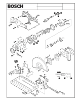
3814 CHOP SAW Pos. Part Number Description {Qty} 2 2 610 355 302 Field 115V 3 2 610 355 301 Armature w/Fan115V 4 2 610 355 335 Switch 5 2 610 355 306 Cord 6 2 610 355 307 Strain Relief 7 2 610 355 342 Clamp 8 2 610 994 082 Nameplate "3814" 9 2 610 994 083 Label "Bosch" 11 2 610 355 310 Cable 13 2 610 010 824 Ball Bearing 14 2 610 023 268 Ball Bearing {2} 15 2 610 355 311 Baffle 16 2 610 355 297 Brush Holder 17 2 610 355 309 Washer 19 2 610 355 349 Baffle 20 2 610 994 505 Gear Housing 21 2 610 355 298 Brush Cap {2} 23 2 610 355 303 Screw {2} 28 2 610 355 343 Key 29 2 610 355 341 Screw {2} 30 2 610 355 337 Screw & Washer {9} 31 2 610 356 706 Nut {11} 32 2 610 355 323 Output Spindle 33 2 610 355 322 Gear 35 2 610 355 313 Needle Bearing 36 2 610 355 338 Screw 37 2 610 352 729 Sleeve 38 2 610 355 317 Gear Housing Cover 39 2 610 355 267 Screw 40 2 610 355 270 Screw 41 2 610 355 268 Screw 42 2 610 355 286 Knob 43 2 610 358 055 Bolt {3} 44 2 610 355 345 Bushing 45 2 610 355 344 Bushing {2} 46 2 610 355 347 Bumper {2} 47 2 610 355 284 Retaining Ring {2} 48 2 610 355 340 Hook 49 2 610 355 279 Chain 50 2 610 994 516 Base Assembly 51 2 610 355 314 Plug {2} 52 2 610 355 348 Roll Pin 53 2 610 355 321 Washer 54 2 610 355 331 Screw {2} 55 2 610 355 320 Retaining Ring 56 2 610 994 510 Pin 57 2 610 328 702 Push Nut 58 2 610 355 280 Roll Pin 59 2 610 355 265 Shaft Service Notes: F/C Pos. 22 60 AW 61 15 62 11 63 11 64 89 65 9 66 9 67 10 68 60 69 61 70 24 71 25 72 65 73 24 74 72 75 25 76 89 77 66 78 89 79 89 80 89 81 52 82 33 83 56 84 89 85 82 98 70 99 89 101 89 103 89 106 63 112 89 114 82 120 82 123 9 126 89 127 9 130 9 132 88 + 145 9 + 146 66 150 65 152 89 154 89 652 9 801 89 66 810 54 811 Part Number 2 610 355 315 2 610 355 316 2 610 355 295 2 610 355 336 2 610 357 149 2 610 355 259 2 610 355 330 2 610 355 278 2 610 355 293 2 610 355 304 2 610 355 269 2 610 355 264 2 610 355 263 2 610 355 271 2 610 355 277 2 610 355 272 2 610 355 290 2 610 355 274 2 610 355 332 2 610 355 325 2 610 355 324 2 610 355 570 2 610 345 391 2 610 355 318 2 610 355 319 2 610 355 299 2 610 355 329 2 610 994 522 2 610 910 022 2 610 355 266 2 610 994 515 2 610 355 289 2 610 994 511 2 610 995 518 2 610 994 509 2 610 355 275 2 610 994 086 2 610 355 258 2 610 355 328 2 610 994 085 2 610 994 084 2 610 910 023 2 610 994 512 2 610 994 513 2 610 355 260 2 610 994 504 2 610 995 539 2 610 995 517 Description {Qty} F/C Spindle Lock Pin 81 Spring 27 Screw 89 Screw {2} 89 Screw 89 Screw {4} 89 Washer {4} 65 Screw {2} 89 Screw {2} 89 Washer {4} 65 Washer 65 Washer {5} 65 Screw {2} 89 Washer {3} 65 Screw {2} 89 Nut {2} 89 Retaining Ring 89 Washer {2} 65 Nut {2} 89 Lock Washer {4} 65 Screw {4} 89 Washer {2} 65 Washer {2} 65 Washer 65 Washer 65 Grommet 9 Lower Guard 92 Cover Plate 70 Flange {2} 65 Spring 27 Lock 9 Crank Screw 9 Fence 9 Support Bracket 62 Clamp Plate 80 Plate 9 Label "Warning" 9 Post {4} 9 Upper Guard 92 Label "Depth" 9 Label "Warning" 9 Bolt 89 Side Cover 92 Support Bracket 62 Wrench 9 Motor Housing Assembly 71 w/pos. 16, 62, 85 Brush Set 26 Handle Assembly 74 + = Not Illustrated * = As Required F/C = Failure Code AW = Refer to AW Labor Time Chart
-
 1
1 -
 2
2
 |
 |
