Bosch HMV9302 Installation Instructions - Page 11
Wall-vented Installation
 |
UPC - 825225830412
View all Bosch HMV9302 manuals
Add to My Manuals
Save this manual to your list of manuals |
Page 11 highlights
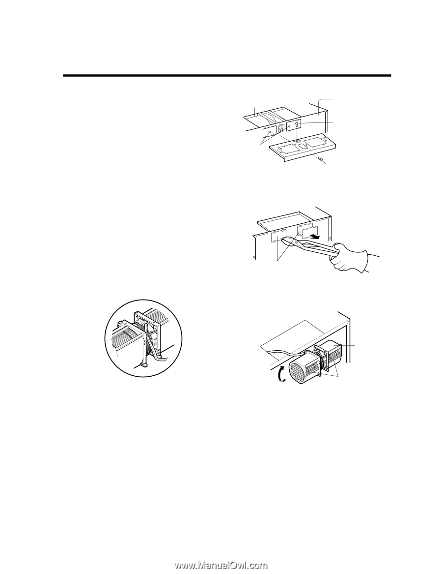
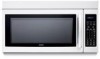
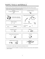
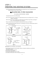
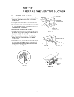
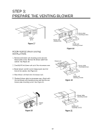
STEP 3: PREPARE THE VENTING BLOWER WALL-VENTED INSTALLATION: 1. Remove one blower unit mounting screw and one blower plate screw. Remove the blower plate from cabinet. See Figure 13. 2. Carefully lift the blower unit out of the microwave oven. 3. Use side cutters or tin snips to cut and remove knockouts "B" from Back plate. Discard knockouts. Be careful not to distort the plate. See Figure 14. 4. Reassemble the blower wire. See Figure 15. 5. Rotate the unit so that the exhaust ports face the rear of the cabinet. See Figure 16. When you insert blower unit, blower wire must be like Figure 16. 6. Place blower unit back into cabinet. Check that the exhaust ports face towards the rear of the cabinet. See Figure 17. 7. Reattach the blower plate to cabinet so the exhaust ports and blower plate opening are aligned. Attach with one blower unit mounting screw and then one blower plate mounting screw. See Figure 18. blower unit back plate blower plate mounting screws Parts "B" blower unit mounting screw Figure 13 Parts "B" Knockout Parts "B" Figure 14 Figure 15 blower unit Figure 16 exhaust ports 11
-
 1
1 -
2
-
3
-
4
-
5
-
 6
6 -
 7
7 -
 8
8 -
 9
9 -
 10
10 -
 11
11 -
 12
12 -
 13
13 -
 14
14 -
 15
15 -
 16
16 -
17
-
18
-
19
-
20
 |
 |