Bosch HUI80553UC Installation Instructions - Page 14
Electrical Installation
 |
View all Bosch HUI80553UC manuals
Add to My Manuals
Save this manual to your list of manuals |
Page 14 highlights
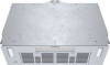
INSTALLATION Electrical Installation CAUTION: Installation work and electrical wiring must be done by qualified person(s) in accordance with all applicable codes and standards, including fire-rated construction. CAUTION: Before installing, turn off power supply at the service panel. Lock service panel to prevent power from being turned on accidentally. 1. Perform the electrical connection as follow: Using UL approved wire nuts, connect BLACK wire from house wiring to BLACK wire from hood connector, WHITE wire from house wiring to WHITE wire from hood connector and GREEN or bare ground wire from house wiring to GREEN wire from hood connector. Then, remove and set aside the screw shown in illustration below for later use. BLACK to BLACK WHITE to WHITE 3. Remove and set aside the filters from the module and frame assembly by opening the latch and fold down the metal grease filter. Simultaneously use your other hand to grasp under the metal grease filter and remove from the frame assembly. 4. Assemble the module and frame assembly to the hood shell; align the keyhole slots to the 3 remaining screws located on the module and frame support. Slide until the screws are engaged in the small part of the keyholes (see left insets). Put back in place the screw removed in step 1, then tighten the 3 remaining screws in order to secure the module and frame assembly to the hood. GREEN to GROUND Hood Connector Remove this screw Align Slide 5. Connect the hood connector to its connector (darker grey part in illustration below). 2. Reassemble the top section of the electrical cover to the hood shell using its 2 retaining screws. Screws English 14
-
 1
1 -
2
-
3
-
4
-
5
-
6
-
7
-
8
-
 9
9 -
 10
10 -
 11
11 -
 12
12 -
 13
13 -
 14
14 -
 15
15 -
 16
16 -
 17
17 -
 18
18 -
 19
19 -
20
-
21
-
22
-
23
-
24
-
25
-
26
-
27
-
28
-
29
-
30
-
31
-
32
-
33
-
34
-
35
-
36
-
37
-
38
-
39
-
40
-
41
-
42
-
43
-
44
-
45
-
46
-
47
-
48
 |
 |
