Bosch KBD-DIGITAL Instruction Manual - Page 22
Console Expander Configuration when Using RS-232 Model, Keyboards
 |
View all Bosch KBD-DIGITAL manuals
Add to My Manuals
Save this manual to your list of manuals |
Page 22 highlights
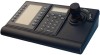
18 en | Installing the IntuiKey Keyboard IntuiKey Keyboard 3.4 After the script has been entered, download the script into the Allegiant CPU. Reset the system by powering the CPU off/on, or by entering Keyboard User Function 15 on an operating keyboard. The specified port begins to operate in the keyboard mode. The port remains in the keyboard mode unless manually cancelled by entering Ctrl-C several times using Windows HyperTerminal program, operating at 9600 baud. The keyboard can now be physically connected to the Allegiant according to details shown in Figure 3.6. Once the keyboard is in communication with the Allegiant, camera and monitor numbers will appear in the LED displays. Allegiant system main CPU bay User-supplied female 9-pin D connector CONSOLE port on Allegiant system must be configured for RS-232 Keyboard mode (refer to text for details) User-supplied cable or other link suitable for full duplex RS-232 transmissions at 9600 baud BOSCH Prod Clr Mon Shot 123 456 789 0 3 m (10 ft) data/ power cable supplied with keyboard Console pin 2 (Rx) to Tx of link or directly to pin 3 of IntuiKey's 9 pin connector Console pin 3 (Tx) to Rx of link or directly to pin 2 of IntuiKey's 9 pin connector Console pin 7 (Gnd) to Data Gnd of link or directly to pin 5 of IntuiKey's 9 pin connector Figure 3.6 Direct Connection to Allegiant's Console/Printer Port The modem on the Allegiant side must be set to an auto answer mode, and the modem on the keyboard side must be set to an originate mode. The modem must also be programmed to dial the phone number or otherwise initiate the connection to the other modem. In some cases, modem settings are configured via dipswitches found on the back of the modem. In other cases, the modem must be connected to a PC for configuration. The below settings represent the dipswitch configuration required for US Robotics Sportster modems. Allegiant-side Modem Dip Switch Setting 1 DOWN 2 UP 3 DOWN 4 UP 5 DOWN 6 DOWN 7 DOWN 8 DOWN Modem Function DTR Override Verbal Result Codes Display Result Codes Echo Offline Commands Suppress Auto Answer Carrier Detect Override Load Factory Defaults Smart Mode Keyboard-side Modem Dip Switch Setting 1 DOWN 2 UP 3 DOWN 4 UP 5 UP 6 UP 7 DOWN 8 DOWN Console Expander Configuration when Using RS-232 Model Keyboards RS-232 model keyboards may be connected to an Allegiant system using the LTC 8712 Series Console Port Expander, as shown in Figure 3.7. An LTC 8712 Series Console Port Expander can be configured to support up to four RS-232 Keyboard connections. Other devices, such as a PC running the Allegiant Master Control software, can be connected to the unused ports of the Port Expander. Because the Port Expander supports only a single baud rate for the external connections, and the RS-232 keyboards require 9600 baud, all external devices connecting to the Port Expander must be configured to for operation at this setting. F.01U.115.018 | 1.92 | 2008.12 Installation Manual Bosch Security Systems, Inc.
-
 1
1 -
2
-
3
-
4
-
5
-
6
-
7
-
8
-
9
-
10
-
11
-
12
-
13
-
14
-
15
-
16
-
 17
17 -
 18
18 -
 19
19 -
 20
20 -
 21
21 -
 22
22 -
 23
23 -
 24
24 -
 25
25 -
 26
26 -
 27
27 -
28
-
29
-
30
-
31
-
32
 |
 |
