Bosch SHEM78W55N Installation Instructions - Page 14
Attach strain relief not provided, Insert the bare copper or green wire, Insert the white neutral - installation manual
 |
View all Bosch SHEM78W55N manuals
Add to My Manuals
Save this manual to your list of manuals |
Page 14 highlights
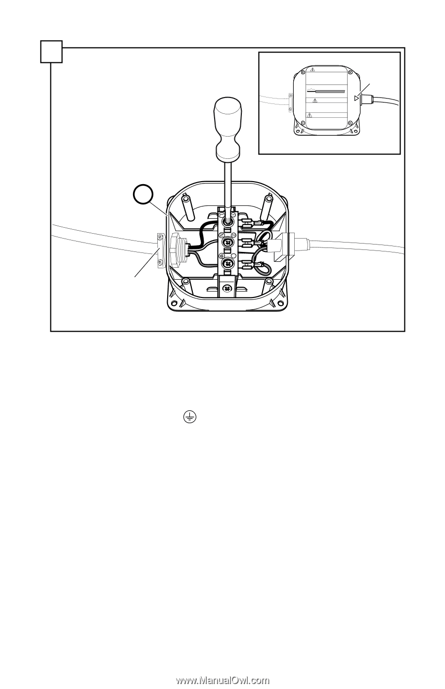
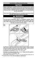
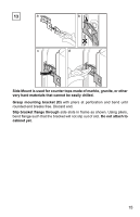
9 KA ADVERTENCIA ESTRICTAMENTE SIGA TODAS LAS INSTRUCCIONES DE ESTE MANUAL. UTILICE SÓLO EL 14 O 12 DE ALAMBRE DE COBRE AWG CON UN GRADO DE LA TEMPERATURA MÍNIMA DE 75 ° C (167 ° F). COLOQUE TODOS LOS CABLES EN LA CAJA DE LA FUENTE DE ALIMENTACIÓN Y LA INSTALACIÓN DE LA CUBIERTA. TORNILLOS DE CONEXIÓN NO SON EXTRAIBLES. 1/2" (13 mm) WIRE STRIP GAGE CALIBRE DE POUR DÉNUDER INDICADOR DE CABLE PELADO WARNING STRICTLY FOLLOW ALL INSTRUCTIONS IN THIS MANUAL. USE ONLY 14 OR 12 AWG COPPER WIRE WITH A MIN. TEMP. RATING OF 75°C (167°F). PLACE ALL WIRING IN THE POWER SUPPLY BOX AND INSTALL COVER. CONNECTION SCREWS ARE NOT REMOVABLE. AVERTISSEMENT OBSERVER TOUTES LES INSTRUCTIONS DE CE GUIDE. UTILISER SEULEMENT DU FIL DE CUIVRE 14 OU 12 AWG AVEC UNE COTE DE TEMPÉRATURE MINIMALE DE 75°C (167°F). PLACER TOUS LES FILS DANS LA BOÌTE D'ALIMENTATION ET REMETTRE LE COUVERCLE. LES VIS DE CONNEXIONS NE SONT PAS AMOVIBLES. arrow view with cover installed strain relief (not provided) Attach strain relief (not provided) to opposite side of junction box. Note: The arrow (shown in the figure above) should align with the power cord. Insert the bare copper or green wire (ground) from the field supply wiring into the ground connection " " of the terminal block and securely tighten the terminal block screw as shown. Insert the white (neutral) wire to the "N" connection of the terminal block and securely tighten the terminal block screw. Insert the black (hot) wire to the "L" connection of the terminal block and securely tighten the terminal block screw. Tighten strain relief. 12
-
 1
1 -
2
-
3
-
4
-
5
-
6
-
7
-
8
-
 9
9 -
 10
10 -
 11
11 -
 12
12 -
 13
13 -
 14
14 -
 15
15 -
 16
16 -
 17
17 -
 18
18 -
 19
19 -
20
-
21
-
22
-
23
-
24
-
25
-
26
-
27
-
28
-
29
-
30
-
31
-
32
-
33
-
34
-
35
-
36
-
37
-
38
-
39
-
40
-
41
-
42
-
43
-
44
-
45
-
46
-
47
-
48
-
49
-
50
-
51
-
52
-
53
-
54
-
55
-
56
-
57
-
58
-
59
-
60
-
61
-
62
-
63
-
64
-
65
-
66
-
67
-
68
-
69
-
70
-
71
-
72
-
73
-
74
-
75
-
76
-
77
-
78
-
79
-
80
-
81
-
82
-
83
-
84
-
85
-
86
-
87
-
88
-
89
-
90
-
91
-
92
-
93
-
94
-
95
-
96
 |
 |