Bose 901 Series II Owner's guide - Page 6
preamplifier
 |
View all Bose 901 Series II manuals
Add to My Manuals
Save this manual to your list of manuals |
Page 6 highlights
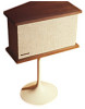
system before the final stage of amplification. The connection method described in this section can be used with virtually all integrated amplifiers, preamplifiers, and receivers. This method usually results in the best signal to noise ratio. For the sake of simplicity, we will call these various components the "control amplifier." The 901 Equalizer is normally connected to your control amplifier as if it were a tape recorder. It utilizes the TAPE MONITOR function and connections of your control amplifier. C.004 TO ratcria O.CC00CO SK0Ct OO NOT 0(o0v( COrt• YO Otelfilv• COIL( cool POO( Otis SON.CorG TO 0ugn MO r14p+lt Plait/E. FIG. 3 Referring to Figure 3, connect the Equalizer according to the instructions in Steps a through n: a. Turn off all power to your equipment. b. If you have a tape recorder, disconnect it from the rear panel of your control amplifier. Instructions in the next section will show you how to reconnect your tape recorder to the system after the Equalizer has been installed. THE FOLLOWING STEPS WILL CONNECT THE EQUALIZER TO YOUR PREAMPLIFIER, RECEIVER, OR INTEGRATED AMPLIFIER. READ THEM CAREFULLY. c. Using one of the cables supplied with the Equalizer, connect the RIGHT channel OUTPUT terminal of the Equalizer to the RIGHT or "B•" channel TAPE MONITOR terminal of your control amplifier. (This terminal may also be labeled TAPE PLAYBACK or TAPE IN.) If your control amplifier has two tape monitor circuits. see Page 9. d. Connect the LEFT channel OUTPUT terminal of the Equalizer to the LEFT or "A" channel tape monitor terminal of your control amplifier. e. Connect the RIGHT channel INPUT terminal of the Equalizer to the RIGHT or "El" channel TAPE RECORD terminal of your control amplifier. (This terminal may also be labeled TAPE OUT or REC OUT.) f. Connect the LEFT channel INPUT terminal to the LEFT or "A" channel TAPE RECORD terminal of your control amplifier. g. Connect the AC power cord of the Equalizer to a switched outlet of your control equipment so that the Equalizer will automatically be switched on or off by the power switch of your integrated ampli• tier, receiver, or preamplifier. If the preceding steps are unclear, it may be due to the different nomenclature which various manufacturers employ. Consult your integrated amplifier. receive:, or preamplifier instructions and refer to the section describing steps for connecting a tape recorder to the tape monitor circuit. Remember that the Equalizer connects like a recorder. 6
-
 1
1 -
 2
2 -
 3
3 -
 4
4 -
 5
5 -
 6
6 -
 7
7 -
 8
8 -
 9
9 -
 10
10 -
 11
11 -
 12
12 -
13
-
14
-
15
-
16
 |
 |