Bose 901 Series III Owner's guide - Page 8
Phasing/Wiring
 |
View all Bose 901 Series III manuals
Add to My Manuals
Save this manual to your list of manuals |
Page 8 highlights
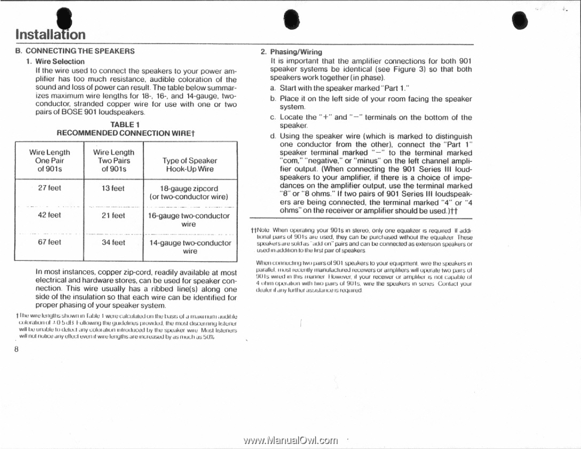
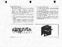
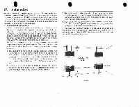
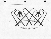
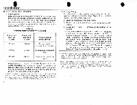
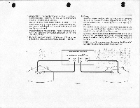
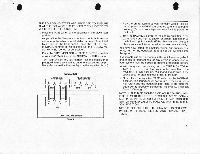
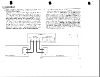
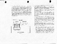
Installion B. CONNECTING THE SPEAKERS 1. Wire Selection If the wire used to connect the speakers to your power amplifier has too much resistance, audible coloration of the sound and loss of power can result. The table below summarizes maximum wire lengths for 18-, 16-, and 14-gauge. twoconductor, stranded copper wire for use with one or two pairs of BOSE 901 loudspeakers. TABLE 1 RECOMMENDED CONNECTION WIREt Wire Length One Pair of 901s Wire Length Two Pairs of 901s Type of Speaker Hook-Up Wire 27 feet ._ . 42 feet 13 feet 21 feet 18-gauge zipcord (or two-conductor wire) 16-gauge two-conductor wire 67 feet 34 feet 14-gauge two-conductor wire In most instances, copper zip-cord, readily available at most electrical and hardware stores, can be used for speaker connection. This wire usually has a ribbed line(s) along one side of the insulation so that each wire can be identified for proper phasing of your speaker system. sin/Willi, tattle I Niel a GA:Waled on VIC Oast; ci a Illamnen andlbte Mk/fallen ol 1 0 5 dlI I 'Mwing Ole guillotines pantided. the nrnl Olsculoold le twN.r win be unable lo cleimt any colixakun introduced by the speaker wire Mml listeners will lid flUIICeany elk,' A wellrl wee lengths ateincreased by asnloch as 5thee 8 S 2. Phasing/Wiring It is important that the amplifier connections for both 901 speaker systems be identical (see Figure 3) so that both speakers work together (in phase). a. Start with the speaker marked "Part 1." b. Place it on the left side of your room facing the speaker system. c. Locate the "+" and "-" terminals on the bottom of the speaker. d. Using the speaker wire (which is marked to distinguish one conductor from the other), connect the "Part 1" speaker terminal marked "-" to the terminal marked "corn." "negative," or "minus" on the left channel amplifier output. (When connecting the 901 Series III loudspeakers to your amplifier, if there is a choice of impedances on the amplifier output, use the terminal marked "8" or "8 ohms." If two pairs of 901 Series III loudspeakers are being connected, the terminal marked "4" or "4 ohms" on the receiver or amplifier should be useditt ft Note When apemen° your 901s in Stereo. Only one equalizer is required II additional pairs of 901s are used, they Can be purchased without the equalizer These speakersare soldas ' add on" pairs and can be connected as extension speakers or used at addition lothe first pair of speakers WILiouwinistaxj Iwo pairsof901 speakers to your equipment wife the speakers in I tianuluctuted receivers or alValets wdl operate Iwo pairs of 90Is wins' in Iles Illannef I lowever. d your receive/ Of aim/Shut is not Callkli/k! of 4 olun /*elation wtlh Iwo Oc/IIS ol 9015, wire the speakers in series Cailacl your dealer d ally ROOM as:a:JaiICU IS legmrud
-
 1
1 -
2
-
 3
3 -
 4
4 -
 5
5 -
 6
6 -
 7
7 -
 8
8 -
 9
9 -
 10
10 -
 11
11 -
 12
12 -
 13
13 -
14
-
15
-
16
-
17
-
18
-
19
-
20
 |
 |