Bose Lifestyle 10 Owner's guide - Page 12
Voltage, International, Models, Connections
 |
View all Bose Lifestyle 10 manuals
Add to My Manuals
Save this manual to your list of manuals |
Page 12 highlights
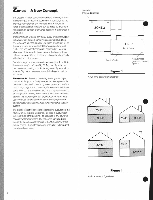
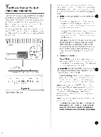
SERIAL DATA OUTPUT A CAUTIO SEE THE BOTTOM. ATTENTION-voa EN role. ZONE 1 ZONE 2 r TAPE L -1\ TIC) , " SOUND L_ JU T Put -+ 1Kr") a•Y INPU 40 ® 0 ® For 120V and Dual Voltage (International) Models The Connections To hear music as it was intended. always take care to insert the left connector into the left jack (white to white), and the right connector into the right jack (red to red). (Reversal will do no harm. but willreverse the soundstage.) Complete the connections to the rear panel of the Lifestyle" music center(see Fig.7), with the MusicCentersAC power cord unplugged. 1. SERIAL DATA OUTPUT: Insert black connector of thelongrnaiial cable leading from the Acoustimass` powered speaker system. Note: These identical jacks are used with the Acoustimass powered speaker system and other auxiliary equipment. 2. ZONE 1: Insert the correctors of the long coaxial cable supplied with your Acoustimass powered speaker system.(Alternatively. Zone 1may beconnected to another Bose" Lifestyle speaker model. See the "Zones - A New Concept' section.) 3. ZONE 2:Insert the connectorsof thelong coaxial cables supplied with the Lifestyle powered speaker system. Note: Thelongcoaxiallinecables suppliedwithpowered Bosesystems carryaudio signalsfrom theMusic Centerto thebuilt-inpowe amplifier 4. TAPE OUT: InsertcccineCtorsof the cable from theinputs of anexternal tape deckinorder torecord from the Lifestylemusic center. 5. TAPE PLAY: Insert connectors of the cable from the outputs of an external tape deck (or other line level component) for playback using the Music Center's tape mode. • 6. VIDEO SOUND: Insert connectors of the cable from the audio outputsof anexternal component.suchas a stereo TV, VCR, or laser videodisc (CD-Video) player. (See the "UsingExternalComponents' section.) 7. AUX: Insert the connectors of a cable from the outputs of any additionalexternal component,suchas amulti-disc CD changer, a second tape player,or anyother linelevel source. 8. FM ANTENNA:Connect the dipole antenna tothese terminals (see Fig. 8). To insert the antenna wires, flip the lever above each terminal up, insert the wire, and return the lever to its original position to lock the wire in place. Note:Ifyouuseanindoorantenna, selecta 75ohmantenna. Formaximumreception, installindoorFMantennasashighas possible, with theirarms fullyextended. Experiment withorientationforthe bestperformance. Reception willgenerally improve when thearms ofthe "rareperpendicular toa lineof sight to theradio transmitter.In fringeareas, anexternalantenna willusuallyimprovereception significantly, regardless of the geographiclocation. Toinstallanantenna, pleaseconsultyour dealer or experi- encedantenna expert.Follow all safety instructions. • 11
-
 1
1 -
2
-
3
-
4
-
5
-
6
-
 7
7 -
 8
8 -
 9
9 -
 10
10 -
 11
11 -
 12
12 -
 13
13 -
 14
14 -
 15
15 -
 16
16 -
 17
17 -
18
-
19
-
20
-
21
-
22
-
23
-
24
-
25
-
26
-
27
-
28
 |
 |
