Bose OmniVector Owner's Guide - Page 2
Loudspeakers
 |
View all Bose OmniVector manuals
Add to My Manuals
Save this manual to your list of manuals |
Page 2 highlights
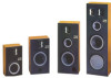
OmniVector Loudspeakers Owner's Guide Introduction Unpacking Wire Selection Thank you forpurchasing OmniVectorthi Unpack each unit carefully, saving the Use standard 18-gaugespeaker wire or loudspeakers. Theiradvanceddesign cartonsand all other packingmaterials "zip cord" toconnect the speakers to andquality construction willgive you for later use. If either unit appears to be your amplifier or receiver. For runs longer manyyears oflisteningpleasure. damaged, do not place the damaged than 20 feet, 16-gauge or thicker wire is To obtain thebestpossibleperformance fromyourspeakers, please take the time to read this guide. unit into operation. Repack the unit(s) recommended. in its original carton and notify your authorized OmniVector dealer immediately. Connection Follow the next procedure to be sure your OmniVector speakers are properly connected to your music system. Refer toFIGURE 1. AMPLIFIER or RECEIVER tOFcTuCmMAiNnNO. RCM 01W4t ClItrul a. Unplug your amplifier or receiver from the power mains before attempt- ing tocongigthe speakers. b. Slightly se re the conductors at the end of each wire. Strip approxi- mately 14 inch of insulation off each PI.'I14n•lai01aeim4-os0,S0,o•ia*t4g•llly•oe0oi4llie•le•l•cl.4••'o••i•/•0•t44a/4ato:eil:l*l • conductor. c. On the beef each speaker is a pair of p type terminals marked • FIGURE1. Speaker connection. + (red) and - (black). These termi- ner. Use the insulation, ribbing or color speakers or amplifier. Bridged wires nals correspond to the positive and coding on the wire to be sure you are create short circuits which can negative output terminalson your am- connecting positive to positive and damage your amplifier. Repair any plifier or receiver. Connect the positive negative to negative. loose wire strands before pluggingin output of each amplifier channel to d. Check very carefully to make the + (red) terminal on the appropriate certain that no loose wire strands are speaker (left or right). Connect the "bridged" across the terminals of the - (black) terminals in a similar man- your amplifier or receiver. Overload Protection All OmniVector loudspeakers incorporate an automatic tweeter protection circuit which prevents damage caused by excessive high-frequency energy. The yellow fiber-optic indicator on the tweeter mounting plate will "light up" whenever this circuit is activated. The light is visible even with the grille assemblyin place. OmniVector Model Two, Three and Four speakers also contain Total System Protection circuitry for increased reliability in high-power applications. A red fiberoptic light indicates activation of this feature. Maintenance OmniVector speakersare finished in durable walnut-grain vinyl veneer. Clean the cabinets by wiping with a Technical Specifications Model One Model Two Recommended Amplifier Power 10-75 watts RMS 15-100 watts RMS Model Three 15-150 watts RMS Model Four 15-200 watts RMS damp cloth and mild soap. The grille assemblies can be carefully brushed or vacuumed if necessary. Nominal Usable Impedance Frequency Response 8 ohms 38-20,000 Hz 8 ohms 32-20,000 Hz 8 ohms 28-20,000 Hz 8 ohms 24-20,000 Hz
-
 1
1 -
 2
2 -
 3
3
 |
 |
