Boss Audio CER2100M User Manual in English - Page 6
Boss Audio CER2100M Manual
 |
View all Boss Audio CER2100M manuals
Add to My Manuals
Save this manual to your list of manuals |
Page 6 highlights
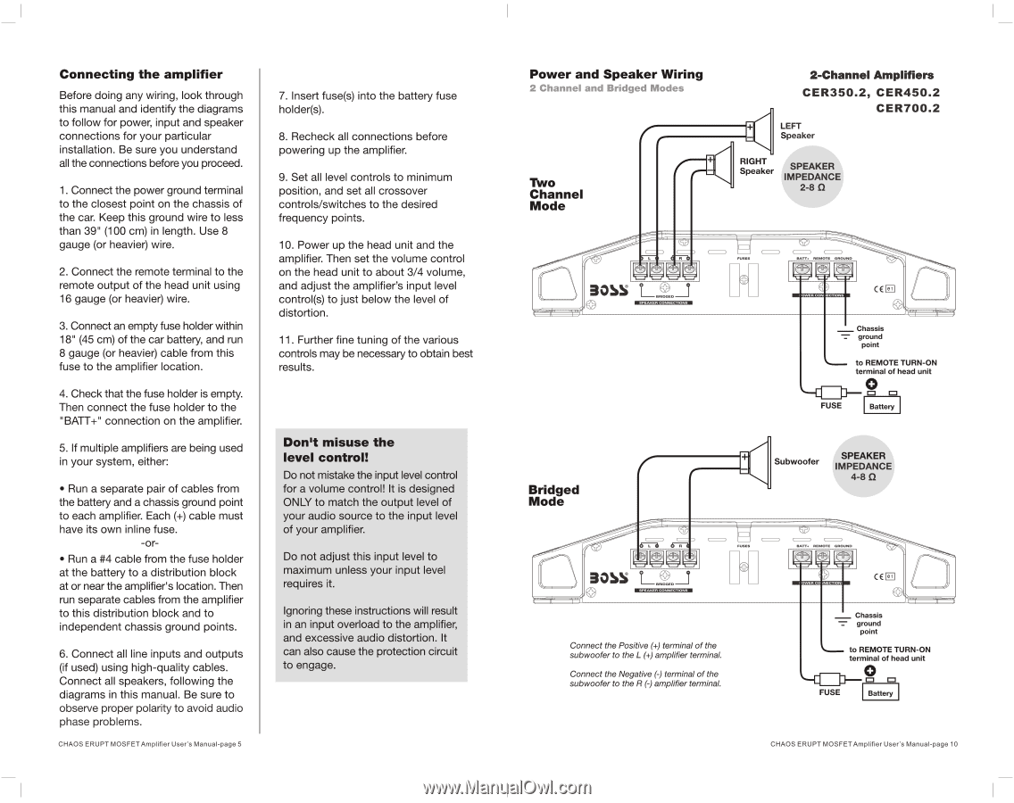
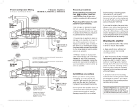
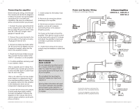
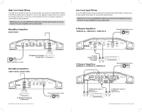
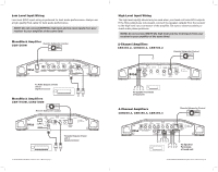
Connecting the amplifier Before doing any wiring, look through this manual and identify the diagrams to follow for power, input and speaker connections for your particular installation. Be sure you understand all the connections before you proceed. 1. Connect the power ground terminal to the closest point on the chassis of the car. Keep this ground wire to less than 39" (100 cm) in length. Use 8 gauge (or heavier) wire. 2. Connect the remote terminal to the remote output of the head unit using 16 gauge (or heavier) wire. 3. Connect an empty fuse holder within 18" (45 cm) of the car battery, and run 8 gauge (or heavier) cable from this fuse to the amplifier location. 4. Check that the fuse holder is empty. Then connect the fuse holder to the "BATT+" connection on the amplifier. 5. If multiple amplifiers are being used in your system, either: • Run a separate pair of cables from the battery and a chassis ground point to each amplifier. Each (+) cable must have its own inline fuse. -or• Run a #4 cable from the fuse holder at the battery to a distribution block at or near the amplifier's location. Then run separate cables from the amplifier to this distribution block and to independent chassis ground points. 6. Connect all line inputs and outputs (if used) using high-quality cables. Connect all speakers, following the diagrams in this manual. Be sure to observe proper polarity to avoid audio phase problems. CHAOS ERUPT MOSFET Amplifier User's Manual-page 5 7. Insert fuse(s) into the battery fuse holder(s). 8. Recheck all connections before powering up the amplifier. 9. Set all level controls to minimum position, and set all crossover controls/switches to the desired frequency points. 10. Power up the head unit and the amplifier. Then set the volume control on the head unit to about 3/4 volume, and adjust the amplifier's input level control(s) to just below the level of distortion. 11. Further fine tuning of the various controls may be necessary to obtain best results. Don't misuse the level control! Do not mistake the input level control for a volume control! It is designed ONLY to match the output level of your audio source to the input level of your amplifier. Do not adjust this input level to maximum unless your input level requires it. Ignoring these instructions will result in an input overload to the amplifier, and excessive audio distortion. It can also cause the protection circuit to engage. Power and Speaker Wiring 2 Channel and Bridged Mode Two Channel Mode 2-Channel Amplifiers CER350.2, CER450.2 CER700.2 LEFT Speaker RIGHT Speake SPEAKER IMPEDANCE 2-8 II 305° © =ma RUGG. 11 RAT, REMOTE GROUND GEE 0' - Chassis ground point to REMOTE TURN-ON terminal of head unit O FUSE Battery Bridged Mode 30NS Connect the Positive (+) terminal of the subwoofer to the L (+) amplifier terminal. Connect the Negative (-) terminal of the subwoofer to the R (-) amplifier terminal. Subwoofer SPEAKER IMPEDANCE 4-8 0 DAT, REMOTE GROUND CEE Chassis ground point FUSE to REMOTE TURN-ON terminal of head unit O =I =I Battery CHAOS ERUPT MOSFET Amplifier User's Manual-page 10
-
 1
1 -
 2
2 -
 3
3 -
 4
4 -
 5
5 -
 6
6 -
 7
7 -
 8
8
 |
 |