Boss Audio MC425BA User Manual V2 - Page 4
MC425IA, Motorcycle/UTV, Amplified, Speaker, System, MC425BA, Motorcycle/In, Installation, Wiring, - review
 |
View all Boss Audio MC425BA manuals
Add to My Manuals
Save this manual to your list of manuals |
Page 4 highlights
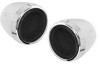
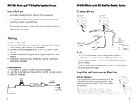
MC425IA Motorcycle/UTV Amplified Speaker System Installation 1. Screw the brackets to the bottom of the speakers. 2. Find a safe, ideal mounting location and fit the brackets over the chosen mounting bars. 3. Fasten the mounting screws after you review the safety of the mounting location. Wiring 1) Remove the seat. 2) Route the fused power leads to the battery. (keep away from moving parts and/or hot exhaust) 3) Connect the RED ring terminal to the +12V post of the battery. 4) Connect the BLACK ring terminal to ground post of the battery. 5) Connect to the connector the white mating connector leading the speaker. Power Switch 1) The switch is used to Power On/off the system. 2) It can be mounted near the volume control for easy access. 3) Reinstall the seat. 17.5AI U U PL SWITCH BATTERY TO SPEAKERS 3 MC425BA Motorcycle/In Amplified Speaker System Connections Right Speaker Left Speaker White Black Audio Cable Switch Black R 3.5mm 3-pole male AUX audio cable To output • uticlat Power cable I 'mo I Red Ground Note: Volume Control Black Ground Battery 1. AUX 3.5 female input connector for output of other audio device like mobile phone, MP3, Ipod and so on. 2. Should use standard 3.5mm 3-pole male plug AUX cable (not included). 3. Stop BT connection first when using the 3.5mm AUX input as an audio source input. Amplifier and Loudspeaker Mounting Install Reminder The components and wiring should not be installed around any moving parts, keep away from ignition parts, fuel lines, or any hot exhaust Speakers should not be installed where they might inhibit safety features on the vehicle (i.e. lights, horns, brake levers, etc...) 4
-
 1
1 -
 2
2 -
 3
3 -
 4
4
 |
 |
