Boss Audio MRGB65B User Manual - Page 4
Wire Diagram, Before Installing This Product - systems
 |
View all Boss Audio MRGB65B manuals
Add to My Manuals
Save this manual to your list of manuals |
Page 4 highlights
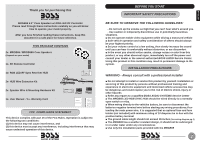
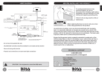
ENGLISH ENGLISH WIRE DIAGRAM YOUR AMPLIFIER REMOTE OUT +12V BLUE GROUND CABLE YOUR RADIO Normally Open ON/OFF ACC switch +12V RED Normally open ACC switch NO C CHASSIS GROUND POINT BLACK METAL FRAME +12V BATTERY YELLOW (not included) OPTIONAL DIRECT BATTERY WIRING CIRCUIT 12FT STRIPPED WIRE NEGATIVE + - SPEAKER 1 + - SPEAKER 2 RGB LED 1 RGB LED 2 INSERT Recommended 16 ~ 18ga Primary Extension Wire (not included) CHASSIS GROUND POINT BATTERY YOUR BATTERY KILL SWITCH OPTIONAL FUSE AND FUSE HOLDER (NOT INCLUDED) 3 AMP FUSE REPLACEMENT WITH ATO TYPE ONLY Splice BUTT connectors RGB SYNC HUB 3A SYNC OUT RGB LED 1 INSERT SYNC IN RGB LED 2 TO CONNECT MORE THAN ONE SET OF MRGB65 TOGETHER, PLUG THE SYNC OUT TO THE SYNC INPUT OF THE NEXT SYSTEM NOTE: ONLY USE SYNC IN/OUT WHEN CONNECTING TWO OR MORE HUB SYSTEMS TOGETHER RGB LED EXTENSION WIRE - Do not touch the speaker flex wire - The RGB HUB controller should be installed in a non-metal and dry location - Secure all wiring with wire ties - Properly seal connections to ensure water tight connections 3 CAUTION!! Do not ground or short the RGB wires BEFORE INSTALLING THIS PRODUCT To avoid potential shorts in the electrical system, be sure to disconnect the (-) battery cable before installation. Use this unit with a 12-volt battery and negative grounding only. Failure to do so may result in a fire or malfunction. When replacing the fuse, be sure to only use a fuse of the rating specified on this product. To avoid short-circuiting, cover any disconnected leads with insulating tape. It is especially important to insulate any unused wires, which if left uncovered may cause a short circuit. When connecting other devices to this product, refer to the manual for the product to be connected. The black cable is ground, make sure to connect the ground wire first. Ensure that the ground cable is properly connected to metal parts of the vehicles body frame or direct to the battery if your vehicle does not have a grounded chassis frame The ground cable of this units power amp and a second powered system must be connected to the frame separately with different screws. If the screw for the ground wire loosens or falls out, it could result in fire or malfunction. TECHNICAL SUPPORT 1-800-999-1236 www.bossaudio.com/support TOOLS NEEDED: - Wrench and/or Pliers - #2 Phillips screwdriver - Crimp tool - Handsaw / Jig Saw - Electrical tape 4
-
 1
1 -
 2
2 -
 3
3 -
 4
4 -
 5
5 -
 6
6
 |
 |
