Brother International HL-720 Service Manual - Page 74
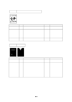
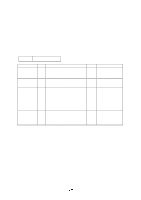
No DC power, Main motor unrotated
 |
View all Brother International HL-720 manuals
Add to My Manuals
Save this manual to your list of manuals |
Page 74 highlights
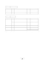
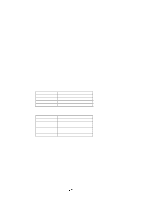
M-2 Possible cause AC power supply Wiring, DC load No DC power li d Step 1 2 Check Is AC power supplied between connectors CN1-L and CN1-N when the power plug is plugged into the outlet? Turn the power switch OFF and disconnect the P4 connector (panel sensor PCB). Measure the voltages between the terminals. Do the measured voltage satisfy the prescribed value in the table below? Result No Yes Remedy Follow the same check procedure of M1 "No AC power supplied". Turn the power switch OFF, connect the connector disconnected, and turn the power switch ON again. If the protector circuit is activated, check the connector, the wiring from the connector, and the DC load. Power supply 3 input unit No Replace the power supply input unit after unplugging the power cord from the power outlet. M-3 Main motor unrotated Possible cause Connection failure of connector Main motor (M1) Panel sensor circuit Step Check 1 Is the connection of connector P5 on the panel sensor PCB correct? 2 Disconnect connector P5 from the panel sensor PCB. Measure the resistance between the connector pins of the main motor by using a circuit tester. Do the measured resistance satisfy the prescribed value in the table below? Result Remedy No Reconnect the connector. No Replace the Main motor. Yes Replace the panel sensor PCB. Replace the Main PCB.
-
 1
1 -
2
-
3
-
4
-
5
-
6
-
7
-
8
-
9
-
10
-
11
-
12
-
13
-
14
-
15
-
16
-
17
-
18
-
19
-
20
-
21
-
22
-
23
-
24
-
25
-
26
-
27
-
28
-
29
-
30
-
31
-
32
-
33
-
34
-
35
-
36
-
37
-
38
-
39
-
40
-
41
-
42
-
43
-
44
-
45
-
46
-
47
-
48
-
49
-
50
-
51
-
52
-
53
-
54
-
55
-
56
-
57
-
58
-
59
-
60
-
61
-
62
-
63
-
64
-
65
-
66
-
67
-
68
-
 69
69 -
 70
70 -
 71
71 -
 72
72 -
 73
73 -
 74
74 -
 75
75 -
 76
76 -
 77
77 -
 78
78 -
 79
79 -
80
-
81
-
82
-
83
-
84
-
85
-
86
-
87
-
88
-
89
-
90
-
91
-
92
-
93
-
94
-
95
-
96
-
97
-
98
-
99
-
100
-
101
-
102
-
103
-
104
-
105
-
106
-
107
-
108
-
109
-
110
-
111
-
112
-
113
-
114
-
115
-
116
-
117
-
118
-
119
-
120
-
121
-
122
-
123
-
124
-
125
-
126
-
127
-
128
-
129
-
130
-
131
-
132
-
133
-
134
-
135
-
136
-
137
-
138
-
139
-
140
-
141
-
142
-
143
-
144
-
145
-
146
-
147
-
148
-
149
-
150
-
151
-
152
-
153
-
154
 |
 |
