Brother International LS2-B891 Parts Catalog - Page 4
Notes, using, parts, CONTENTS
 |
View all Brother International LS2-B891 manuals
Add to My Manuals
Save this manual to your list of manuals |
Page 4 highlights
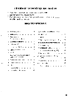
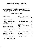
Notes for using this parts book 1. This book is applicable to sewing machines which have the same plate number as shown on the cover of this book (or correction sheet). 1. This book was prepared based on information available in May 1998. 2. Parts are subject to changes in design without prior notice. 3. Parts supplied as complete assemblies are circled by a dotted line CONTENTS A . Machine body B . Upper shaft mechanism C . Upper shaft and thread take-up mechanism D . Needle bar rocking mechanism E . Presser foot mechanism F . Feed mechanism G . Presser foot lifter mechanism H . Quick reverse mechanism 1. Alternating presser foot lifter mechanism (-705) K. Upper feed mechanism L. Feed shaft mechanism M . Gauge parts N . Quick reverse mechanism (-705) P. Rotary hook shaft timing mechanism 1 Q . Vertical shaft and lower shaft mechanism 5 R . Lubrication 7 5. Bobbin winder mechanism 7 T . Tension release mechanism 9 U . Thread trimmer mechanism (-705) 11 V . Thread tension 13 W . Knee switch mechanism (-705) 15 X . Manual switch mechanism (-705) Y. Air pressure mechanism (-705) 15 AA . Presser foot actuator mechanism 17 (-705) 19 Z. Accessories 21 Wa . Warning labels 21 Index 23 25 .J 27 29 29 31 33 35 35 37 37 39 41 42
-
 1
1 -
 2
2 -
 3
3 -
 4
4 -
 5
5 -
 6
6 -
 7
7 -
 8
8 -
 9
9 -
 10
10 -
11
-
12
-
13
-
14
-
15
-
16
-
17
-
18
-
19
-
20
-
21
-
22
-
23
-
24
-
25
-
26
-
27
-
28
-
29
-
30
-
31
-
32
-
33
-
34
-
35
-
36
-
37
-
38
-
39
-
40
-
41
-
42
-
43
-
44
-
45
-
46
-
47
-
48
-
49
-
50
-
51
-
52
-
53
-
54
-
55
-
56
 |
 |
