Brother International MFC 8500 Service Manual
Brother International MFC 8500 - B/W Laser - All-in-One Manual
 |
UPC - 012502603832
View all Brother International MFC 8500 manuals
Add to My Manuals
Save this manual to your list of manuals |
Brother International MFC 8500 manual content summary:
- Brother International MFC 8500 | Service Manual - Page 1
FACSIMILE EQUIPMENT SERVICE MANUAL MODEL: MFC8500/FAX4100/FAX4750e/FAX5750e MFC9660/FAX8360P - Brother International MFC 8500 | Service Manual - Page 2
© Copyright Brother 2002 All rights reserved. No part of this publication may be reproduced in any form or by any means without permission in writing from the publisher. Specifications are subject to change without notice. All products and company names mentioned in this manual are trademarks or - Brother International MFC 8500 | Service Manual - Page 3
DESCRIPTION INSTALLATION THEORY OF OPERATION DISASSEMBLY/REASSEMBLY AND LUBRICATION MAINTENANCE MODE ERROR INDICATION AND TROUBLESHOOTING Appendix 1. Appendix 2. Appendix 3. Appendix 4. EEPROM Customizing Codes Firmware Switches (WSW) Circuit Diagrams Toner Cartridge Weight This manual describes - Brother International MFC 8500 | Service Manual - Page 4
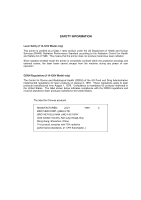
printer is completely confined within the protective housings and external covers, the laser beam cannot escape from the machine during any phase of user The label for Chinese products MANUFACTURED: JULY 1999 C BROTHER CORP. (ASIA) LTD. BROTHER BUJI NAN LING FACTORY Gold Garden Industry, Nan - Brother International MFC 8500 | Service Manual - Page 5
CHAPTER I. GENERAL DESCRIPTION - Brother International MFC 8500 | Service Manual - Page 6
CHAPTER I. GENERAL DESCRIPTION CONTENTS 1. EQUIPMENT OUTLINE I-1 1.1 External Appearance and Weight I-1 1.2 Components ...I-1 2. SPECIFICATIONS...I-2 - Brother International MFC 8500 | Service Manual - Page 7
1. EQUIPMENT OUTLINE 1.1 External Appearance and Weight The figure below shows the equipment appearance and approximate dimensions. Weight: Machine proper Machine (incl. drum unit & toner cartridge) In package w/o 2nd cassette 10.5 kg 12.0 kg 16.5 kg w/ 2nd cassette 14.0 kg 15.5 kg 22.0 kg 1.2 - Brother International MFC 8500 | Service Manual - Page 8
Volume Figures of One-Touch & Speed Dial Resisterable Number Of Characters MFC8500 Laser (ZLe) 14,400(Fax) Approx. 6 G3 MH/MR/MMR 5.8"-8.5"/2.75"-8.5" 30 16 Characters x 2 Lines Yes Yes (9 hours) 8 MB N / A N / A N / A 250 250 (User Option) 17.1x17.4x12.7 inches 435x442x323 mm 26.4 lbs/(12 kg - Brother International MFC 8500 | Service Manual - Page 9
ITU-T Group Coding Method Input/Output Width ADF(pages) LCD Size On-Screen Programming Back up Clock Memory Capacity(MB) Back up Memory Memory Security Optional Memory Paper Capacity(sheets) Additional Paper Capacity(sheets) Dimensions (WxDxH) Weight Color Standby Mode PC-Fax Protocol Compliance - Brother International MFC 8500 | Service Manual - Page 10
Batch Transmission Auto Reduction Out-of-Paper Reception *2 Dual Access ECM(Error Correction Mode) ITU SUB Addressing Group Dial Resend After Receive Error Signal Confidential Station ID Off Hook Alarm Remote Maintenance Call Reservation Over Manual TX RX Mode Indication Resolution Indication - Brother International MFC 8500 | Service Manual - Page 11
Paper Reception *2 Dual Access ECM(Error Correction Mode) ITU SUB Addressing Group Dial Resend After Receive Error Signal Confidential Station ID Off Hook Alarm Remote Maintenance Call Reservation Over Manual Approx. 2 sec./page (A4:standard) Yes (282 locations) Yes Yes up to 600 pages(JBIG) Yes Yes - Brother International MFC 8500 | Service Manual - Page 12
Print Language Emulation Resident Fonts Fonts Disk Based Paper Handling Size Manual Feed Slot Other Paper Type Sheet Weight (Paper Cassette) (Manual Slot) Printer Driver Utility Software MFC8500 Yes Mono Laser(ZL) 600x600 up to 15 (Letter size) 150 Windows GDI(600x600) PCL4 24 Bitmap (PCL4 Comp - Brother International MFC 8500 | Service Manual - Page 13
Paper Type Sheet Weight (Paper Cassette) (Manual Slot) Printer Driver Utility Software (3/4) FAX4750e FAX5750e Available with Web download Yes - standard Mono Mono Laser(ZLe) Laser(ZLe) 600x600 600x600 up to 15(Letter size) up to 15(Letter size) 150 150 Windows GDI(600x600) Windows - Brother International MFC 8500 | Service Manual - Page 14
for Win95/98(SE)/Me/XP) Network Print Software (NetBIOS/SMTP) For iMAC Printer Driver (Brother) TWAIN (TII/Brother) Viewer (ScanSoft PaperPort) POP UP menu PC Fax (Brother) Remote Setup Auto Email Printing Support OS version Printer 8.5 - 9.1 Others 8.6 - 9.2 MFC8500 Yes Yes Yes Yes Yes Yes Yes Yes - Brother International MFC 8500 | Service Manual - Page 15
Model Name APPLICATION SOFTWARE For Windows Printer Driver (Brother) TWAIN (Brother) POP UP menu PC Fax (Brother; both TX & RX ) Remote Setup Auto Email Printing Support OS version (Win95/98(SE)/Me, WinNT4.0/2K/XP) BRAdmin Professional Network Print Software (LRP) for Win95/98(SE)/Me/XP) Network - Brother International MFC 8500 | Service Manual - Page 16
Feature Transfer Method Figures of One-touch & Speed Dial Resisterable Number of Characters MFC-9660 Laser (ZLe) 33,600(Fax) Approx.2 ( Brother#1, JBIG ) Super G3 MH/MR/MMR/JBIG 5.8"-8.5"/2.75"-8.5" Up to 30 16 Characters x 2 Lines Yes Yes (9 hours) 8 Mbyte(RAM) Yes( Max 4 days) Yes( 16/32 MByte - Brother International MFC 8500 | Service Manual - Page 17
Paper Reception (ITU-T#1 Chart) *1 Dual Access ECM(Error Correction Mode) ITU SUB Addressing Resend After Receive Error Signal Confidential Station ID Off Hook Alarm Remote Maintenance Call Reservation Over Manual Interface MFC-9660 page (A4 :standard) Yes (182 locations) Yes Yes Up to 500 pages - Brother International MFC 8500 | Service Manual - Page 18
Paper Handling Size Manual Feed Slot Other Paper Type Sheet Weight (Paper Cassette) (ADF) (Manual Slot) Printer Driver Utility Software Toner Life (Standard Yield : TN-6300) (High Yield : TN-6600) Drum System MFC-9660 Mono Laser(ZLe) 600x600 up to 14 250 250 (User Option) 150 Windows GDI(600x600 - Brother International MFC 8500 | Service Manual - Page 19
CENTER BUNDLED SOFTWARE For Windows Support OS version Printer Driver Viewer TWAIN PC Fax For MAC Support OS version Printer Driver Viewer TWAIN PC Fax Printer Others MFC-9660 N / A N / A N / A N / A N / A N / A Yes Yes No Yes N/A N/A N/A N/A Win95/98/98SE/Me, WinNT4.0/2K Yes(Brother ) Yes - Brother International MFC 8500 | Service Manual - Page 20
CHAPTER II. INSTALLATION - Brother International MFC 8500 | Service Manual - Page 21
CHAPTER 2 INSTALLATION CONTENTS 1. INSTALLING THE UPDATE DATA TO THE FACSIMILE MACHINE II-1 2. SETTING ID CODES TO FACSIMILE MACHINES II-3 - Brother International MFC 8500 | Service Manual - Page 22
it with the lock wires. (4) Connect the other end of the interface cable to the printer port of your computer and secure it with the two screws. (5) While pressing the 5 key on the machine's control panel, plug the machine's power cord into a wall socket (or turn on the power ON/OFF switch if - Brother International MFC 8500 | Service Manual - Page 23
the update data onto the flash ROM of the facsimile machine NOTE: The following is an installation procedure example on a PC that is running Windows 95/98. (1) Copy the update data and transfer utility onto the desired directory of the hard disk. e.g., C:\UPDATE (2) Click the Start button, point - Brother International MFC 8500 | Service Manual - Page 24
here. For models covered by this manual, set serial numbers given to individual machines as ID codes. (*ID codes are essential when more than one machine is connected to a single PC via USB.) Connecting the facsimile machine to your PC (See the illustration on page II-1.) (1) Make sure that your PC - Brother International MFC 8500 | Service Manual - Page 25
CHAPTER III. THEORY OF OPERATION - Brother International MFC 8500 | Service Manual - Page 26
-3 2.1.2 Scanner...III-3 2.2 Laser Printing Mechanism III-4 2.2.1 Paper pick-up and registration mechanism III-4 2.2.2 Print process mechanism -7 (4) Transferring process III-7 2.2.3 Heat-fixing mechanism III-8 2.2.4 Paper ejecting mechanism III-9 2.3 Sensors and Actuators III-10 3. CONTROL - Brother International MFC 8500 | Service Manual - Page 27
1. OVERVIEW *Not provided on those models without handset. III - 1 - Brother International MFC 8500 | Service Manual - Page 28
the following mechanisms: n SCANNER MECHANISM - Document feeding and ejecting mechanism - Document scanning mechanism n LASER PRINTING MECHANISM - Paper pick-up and registration mechanism - Print process mechanism (consisting of charging, exposing, developing, and transferring processes) with - Brother International MFC 8500 | Service Manual - Page 29
(which consists of the document take-in roller ASSY, nip-related parts, separation roller ASSY, and ADF parts) feeds those documents into the equipment, starting from the bottom sheet (first page) to the top (last page), page by page. Each document advances with the document feed roller ASSY to the - Brother International MFC 8500 | Service Manual - Page 30
a time. After the leading edge of the pulled-in paper passes through the manual insertion sensor actuator, the paper is further fed for the specified time length. Accordingly, the leading edge will reach the paper feed roller where the paper skew will be eliminated. At the 3rd stage, the controller - Brother International MFC 8500 | Service Manual - Page 31
Print process mechanism The print process unit works with laser beam, electrical charges, and toner. The graph below shows the transition of electrical charge on the surface of the laser-sensitive drum through the four processes: charging, exposing, developing, and transferring processes. III - 5 - Brother International MFC 8500 | Service Manual - Page 32
frame. (2) Exposing process When the laser-sensitive drum holds a positive electrical charge, the laser beam issued from the laser unit scans the drum according to the print image to expose the drum surface for neutralizing the spots where black should be, forming an electrostatic latent image. III - Brother International MFC 8500 | Service Manual - Page 33
roller may be contaminated with toner since not all the toner particles on the drum are transferred onto the paper but some toner particles will remain on the drum and will be transferred from the drum to the transfer roller. If paper jam or other errors occur, the toner image fails to stick to - Brother International MFC 8500 | Service Manual - Page 34
passes between the heater roller and the pressure roller in the heat-fixing unit, the heater roller fuses the toner on the paper. The controller monitors the internal resistance of the heater thermistor to keep the surface temperature of the heater roller constant by turning the halogen heater - Brother International MFC 8500 | Service Manual - Page 35
the specified period after the leading edge of the paper pushes down the paper ejection sensor actuator, then the controller will interpret such an event as a paper jam inside the heat-fixing unit and display a jam error on the LCD. The paper will be turned over along the outer chute and ejected - Brother International MFC 8500 | Service Manual - Page 36
Actuators This machine has 12 sensors: nine photosensors, two thermistors and a mechanical switch as described below. Sensor name Document front sensor Document rear sensor Manual insertion sensor Registration sensor Cassette sensor Paper ejection sensor Toner sensor Cover sensor Jam sensor Heater - Brother International MFC 8500 | Service Manual - Page 37
* Provided on models equipped with a handset. NOTE: Jam sensor The machine has a jam sensor (not shown in the above illustration) which is on the heat-fixing unit. Location of Sensors and Actuators III - 11 - Brother International MFC 8500 | Service Manual - Page 38
PCB *4 Main motor Toner sensor PCBs (Toner sensor LED, light-receiver, and cover sensor) LASER PRINTING UNIT 2nd paper cassette *4 2nd cassette sensor PCB (2nd cassette sensor & 2nd registration sensor) Solenoid *1 Provided on models supporting LAN interface. *2 Models supporting the video capture - Brother International MFC 8500 | Service Manual - Page 39
CHAPTER IV. DISASSEMBLY/REASSEMBLY AND LUBRICATION - Brother International MFC 8500 | Service Manual - Page 40
IV-11 1.8 Top Cover (Exit Roller, Speaker, and Document Guides IV-15 1.9 Handset Mount and Hook Switch PCB (for models equipped (for models supporting video capture IV-24 1.12 Front Cover Front Sub Cover (for models not supporting video capture IV-25 1.13 Outer Chute and Paper Pinch Rollers - Brother International MFC 8500 | Service Manual - Page 41
and 2nd Cassette Relay PCB IV-56 1.24 Toner Sensor (light-receiver) PCB and Toner Sensor (LED) PCB IV-58 1.25 Gears and Paper Pick-up Roller IV-59 1.26 Paper Feed Roller ASSY IV-60 1.27 Clutch Levers, Cassette Guide L, and Solenoid IV-61 1.28 Paper Cassette IV-62 1.29 Cleaning of High-voltage - Brother International MFC 8500 | Service Manual - Page 42
problems by mishandling, observe the following precautions during maintenance work. (1) Unplug the power cord from the power outlet before accessing parts or units inside the machine. When having access to the power supply, be sure to unplug the power cord from the power outlet. (2) When servicing - Brother International MFC 8500 | Service Manual - Page 43
line, - the modular jack of the curled cord (and remove the handset)*, - the PC interface cable, and - the modular jack of an external telephone set if connected. (Not shown below.) (2) Remove - the document support, - the document tray, - the paper cassette, and - the drum unit (with toner - Brother International MFC 8500 | Service Manual - Page 44
(NOTE 3) On the heat-fixing unit are a jam sensor and heater thermistor. (NOTE 4) The main paper ejection sensor PCB is the paper ejection sensor (photosensor). (NOTE 6) On the engine PCB are these photosensors: - Registration sensor - Manual insertion sensor - Cassette sensor (NOTE 7) On the toner - Brother International MFC 8500 | Service Manual - Page 45
cover. (2) Remove the three screws (two "a" and one "b") from the rear cover. Screw "b" is provided on those models available with a 2nd paper cassette (as an option or standard). (3) Lightly pressing sections "X," pull out the rear cover. "a" and "b": Screw, pan (washer) M4x10DB 1.2 Access Plates - Brother International MFC 8500 | Service Manual - Page 46
1.3 Control Panel ASSY (1) Slightly open the control panel ASSY. (2) Push the right and left arms of the control panel ASSY outwards (in the direction of arrow ) with your thumbs, then open the control panel ASSY further (arrow to unhook those arms from bosses "x" provided on the scanner frame ASSY) - Brother International MFC 8500 | Service Manual - Page 47
spring), remove the screw. (3) To remove the nip-related parts (nip piece and spring), push down the nip piece (arrow ) and then press either side of the piece inwards (arrow ). (4) To remove the document pressure bar, press either of supports "a" provided on the panel rear cover inwards and then - Brother International MFC 8500 | Service Manual - Page 48
(7) Remove the two screws from the panel rear cover. (8) Unhook the panel rear cover from eight "X" latches provided on the control panel and lift up the panel rear cover. (9) Fully turn the document front sensor actuator to the rear and take it out. (10) Unhook the document sensor PCB from two "Y" - Brother International MFC 8500 | Service Manual - Page 49
and requires replacement. Reassembling Notes • Before reinstalling the LCD to the control panel, wipe fingerprints or dust off the LCD surface and control panel window with a soft cloth. • A new LCD is covered with a protection sheet. Before installing it, remove the protection sheet. IV - 8 - Brother International MFC 8500 | Service Manual - Page 50
1.5 Document Feed Roller ASSY, Document Ejection Roller ASSY, and Pinch Rollers (1) Lightly push arm rib "a" to the rear, then pull the document feed roller ASSY to the left and upwards. (2) Lightly push arm rib "b" to the rear, then pull the document ejection roller ASSY to the left and upwards. - Brother International MFC 8500 | Service Manual - Page 51
1.6 CIS Unit (1) Lightly pull up the arm, move the CIS unit to the right, and lift up the left edge of the CIS unit gently. NOTE: Do not lift up the left edge exceeding 30 mm to prevent the CIS harness connector on the CIS unit from getting broken. (2) While holding up the CIS unit, disconnect the - Brother International MFC 8500 | Service Manual - Page 52
1.7 Scanner Frame ASSY (Scanner Motor, Scanner Drive Unit, Document Take-in Roller, Separation Roller, Pressure Rollers, and Control Panel Locks) (1) Remove the two screws from the scanner frame ASSY. (2) Lift up the front edge of the scanner frame ASSY and pull the ASSY towards you to release the - Brother International MFC 8500 | Service Manual - Page 53
(4) Turn the scanner frame ASSY upside down. (5) Remove the screw from the scanner motor and turn the motor (as shown below) to release it from the latch. (6) Remove the two screws and take off the scanner drive unit. IV - 12 - Brother International MFC 8500 | Service Manual - Page 54
(7) Remove the document take-in roller gear (in the direction of arrow Q) by pulling its pawls outwards. Slightly push down the arm (arrow R) and shift the document take-in roller shaft to the left (arrow S) and take it up. Then shift the document take-in roller to the left and take it up. (8) - Brother International MFC 8500 | Service Manual - Page 55
roller shaft should be a white one; the separation roller shaft should be a black one. When setting these shafts to their rollers, fit the groove provided in with the connector facing up and then secure it with the screw. (See page IV-12.) • When setting the scanner frame ASSY back into place, be - Brother International MFC 8500 | Service Manual - Page 56
1.8 Top Cover (Exit Roller, Speaker, and Document Guides) (1) Disconnect the hook switch harness* and speaker harness from the main PCB. *For models equipped with a handset (2) Remove the harness support rubbers to release the hook switch harness*. (3) Release the scanner motor harness and CIS - Brother International MFC 8500 | Service Manual - Page 57
(4) Remove two screws "a." (5) Open the front cover and remove two screws "b." (6) Pull the tabs of the top cover to the front and upwards (in the direction of arrows ) to release them from the bosses provided on the main cover. (7) Insert the tip of a flat screwdriver and unhook the latches of the - Brother International MFC 8500 | Service Manual - Page 58
(8) Turn the top cover upside down. (9) Peel off anti-static brushes. NOTE: Once removed, they will become unusable and new parts will have to be put back in. (10) As shown below, warp the gear-equipped end of the exit roller and remove it. (11) Unhook - Brother International MFC 8500 | Service Manual - Page 59
of the top cover, then remove the document guides L and R as shown below. Reassembling Notes • When reinstalling the paper guides, set them into place, pull them outwards (in the direction of arrows ), and then secure them with the spring, guide gear, and screw (arrow ). IV - 18 *For models - Brother International MFC 8500 | Service Manual - Page 60
square and round cutouts ("y" and "z") provided in the top cover, respectively. If the scanner motor harness or CIS harness has been taken out from the machine, first put it into the respective cutout ("Y" or "Z") provided in the left rear corner of the main cover with the core-equipped end down and - Brother International MFC 8500 | Service Manual - Page 61
• When connecting the speaker harness and hook switch harness* to the main PCB: - route the hook switch harness* through the ferrite core of the speaker harness, - make sure that the panel-main harness, speaker harness, and hook switch harness* are routed through the cutout provided in the bottom - Brother International MFC 8500 | Service Manual - Page 62
1.9 Handset Mount and Hook Switch PCB (for models equipped with a handset) Side Cover (for models without handset) (1) Remove the two screws from the handset mount* or side cover**. (2) Twist the handset mount* or side cover** so that it tilts over to the left and its upper end works out of the - Brother International MFC 8500 | Service Manual - Page 63
above. Take care not to pinch the harness between the upper and lower mounts. • Make sure that the hook switch harness is routed along the guides on the top cover. IV - 22 - Brother International MFC 8500 | Service Manual - Page 64
1.10 Paper Sub Tray (1) Turn the paper sub tray up (in the direction of arrow Q). (2) Warp the sub tray and lift it up (arrows R and S). IV - 23 - Brother International MFC 8500 | Service Manual - Page 65
1.11 VC Cover, VC Bracket, and VC Connector PCB (for models supporting video capture) (1) Remove two screws ("a" and "b"), then take off the VC cover. (2) Remove screw bind S M3x8 "c" and "d": Taptite, cup S M3x6 n Reassembling Notes • The routing of the VC harness is shown on page IV-27. IV - 24 - Brother International MFC 8500 | Service Manual - Page 66
1.12 Front Cover Front Sub Cover (for models not supporting video capture) (1) For models not supporting video capture: Remove the screw and take off the front sub cover from the front cover. (2) Remove the screw from the left bottom of the - Brother International MFC 8500 | Service Manual - Page 67
Outer Chute and Paper Pinch Rollers (1) Pull up the outer chute and open it (in the direction of arrow Q). (2) Remove the chute springs from the hooks provided on the main cover (arrow R), then lift up the outer chute (arrow S). (3) Remove the paper pinch rollers, their supports, and their springs - Brother International MFC 8500 | Service Manual - Page 68
1.14 Main Cover (1) Remove two screws "a" from the front side of the main cover. (2) Remove two screws "b" from the rear side of the main cover, and then pull corner edges "X" outwards to dislocate the main cover from the main chassis. Make sure that the cutout provided in the main cover is - Brother International MFC 8500 | Service Manual - Page 69
1.15 Switch Cover (1) Push the locks of the switch cover as shown below and remove it. IV - 28 - Brother International MFC 8500 | Service Manual - Page 70
the factory. Do not disturb it. "a" and "b": Taptite, cup S M3x16 n Reassembling Notes • Before putting the laser unit back into place, check for any toner particles, paper dust or dirt, and clean them out. • After routing the polygon motor harness and laser flat cable, tape them onto the laser unit - Brother International MFC 8500 | Service Manual - Page 71
harness, and VC harness* from the harness duct. (3) Unhook the harness duct from the main chassis in the directions of arrows Q and R. *Provided on models supporting video capture IV - 30 - Brother International MFC 8500 | Service Manual - Page 72
(4) Remove three screws (two "a" and one "b"). (5) Disconnect the long heater wire (of the heater harness) from the upper center of the heat-fixing unit. (6) Disconnect the short heater wire (of the heater harness) from the left end of the heat-fixing unit. (7) Lift up the heat-fixing unit and - Brother International MFC 8500 | Service Manual - Page 73
off the star wheel holder ASSY. Heat-fixing unit Screw, bind M3x10 Star wheel holder ASSY FU front paper guide Screw, bind M3x10 (3) Release the heater thermistor harness from the three harness guides provided on the underside of the heat-fixing unit. (4) Remove the two screws from the top of the - Brother International MFC 8500 | Service Manual - Page 74
(6) Separate the lower FU frame from the upper one. Boss Hook Upper FU frame Boss Lower FU frame Hook (7) Remove the screw securing the lamp lock plate at the gear side of the upper FU frame. At the other side, loosen the screw. (8) Slightly lift up the right-hand end of the heater roller and - Brother International MFC 8500 | Service Manual - Page 75
, remove the bushing 25. CAUTION: Do not touch the surface of the heater roller. If you have touched it, clean it thoroughly with dry, lint-free cloth. Bushing 25 Heater roller Gear side Retaining ring 25 IV - 34 Bushing 25 Washer 25 HR gear 34 - Brother International MFC 8500 | Service Manual - Page 76
NOTE: When setting the heater roller to the upper FU frame, fit the two ribs of the bushing 25 onto the bosses provided on the FU frame as shown below. HR gear 34 Bushing 25 Rib Heater roller Boss NOTE: At the gear side of the heater roller, fit bushing 25 onto the heater roller with the 0.5 mm - Brother International MFC 8500 | Service Manual - Page 77
NOTE: When setting the heater roller into the upper FU frame, take care not to damage the heater roller with the four hooks. Hooks Heater roller Hooks Upper FU frame (11) Remove the cleaner ASSY and cleaner spring from the upper FU frame. Cleaner ASSY Cleaner spring Upper FU frame IV - 36 - Brother International MFC 8500 | Service Manual - Page 78
(12) From the lower FU frame, gently lift up the right end of the pressure roller 25 and remove it. Pressure roller 25 Lower FU frame (13) At each of the right and left ends of the lower FU frame, push down the PR bushing to incline it inwards and take it out. Remove the PR springs also. (14) At - Brother International MFC 8500 | Service Manual - Page 79
provided on the upper FU frame. Then remove the screw and take off the thermistor. Harness guides Thermistor Upper FU frame Taptite, bind B M3x12 NOTE: When setting the thermistor into the upper FU frame, insert it in the direction shown below. Upper - Brother International MFC 8500 | Service Manual - Page 80
(17) From the upper FU frame, remove the screw and take off the idle gear 13. Then slide the ejection roller to the left and take it out to the front. Upper FU frame Taptite, B M2.3x10 Ejection roller Idle gear 13 (18) Unlatch each of the four ejection pinch roller holders R and L from the upper - Brother International MFC 8500 | Service Manual - Page 81
(19) Remove a pair of ejection pinch rollers from each of the ejection pinch roller holders R and L. Ejection pinch rollers Ejection pinch rollers Ejection pinch roller holder R Ejection pinch roller holder L (20) Remove the screw from each of the four claw holder plates and take them off. Next - Brother International MFC 8500 | Service Manual - Page 82
then remove it in the direction of the arrow shown below together with the ejection actuator spring. Paper ejection sensor actuator Ejection actuator spring Lower FU frame NOTE: When setting the paper ejection sensor actuator and its spring, make sure that they are fitted into place as illustrated - Brother International MFC 8500 | Service Manual - Page 83
(22) From the upper FU frame, remove the screw, slightly lift up the shutter of the ejection actuator 3, and remove the jam sensor PCB. Screw, bind B tite 3x10 Ejection actuator 3 Jam sensor PCB Upper FU frame (23) Turn the ejection actuator 3, move it to the right, and lift it up and out of - Brother International MFC 8500 | Service Manual - Page 84
Upper FU frame n Reassembling Notes • A new heat-fixing unit will be provided with the heater thermistor harness being taped to the unit. Before installing the unit, remove the tape. • If you remove and reinstall the heat-fixing unit because of any failure, make the equipment enter the maintenance - Brother International MFC 8500 | Service Manual - Page 85
1.18 Fan (1) Disconnect the fan harness from the engine PCB. (2) Remove two screws, take out the heater wires from the latch of the fan duct, and take off the fan duct together with the fan. IV - 44 - Brother International MFC 8500 | Service Manual - Page 86
(3) As shown below, pull the fan duct outwards and take out the fan. n Reassembling Notes • Put the fan back into place so that the rating label faces outwards and upside down. • Route the heater wires through the latch of the fan duct as shown on the previous page. IV - 45 - Brother International MFC 8500 | Service Manual - Page 87
and spring, and then disconnect the main motor harness. (3) Remove the front cover link and idle gear 56 from the main chassis. *Provided on models supporting video capture IV - 46 - Brother International MFC 8500 | Service Manual - Page 88
(4) Remove four screws and take off the main motor ASSY from the drive gear ASSY. n Reassembling Notes • If you have removed the gear 39/98 from the drive gear ASSY, hook the spring as shown below. IV - 47 - Brother International MFC 8500 | Service Manual - Page 89
the main PCB. European version: Disconnect the main-NCU harness and main-NCU harness 2 from the main PCB. See the illustration given on the next page. (3) Remove the screw from the NCU PCB and take out the PCB. IV - 48 - Brother International MFC 8500 | Service Manual - Page 90
-NCU harness 2 between the NCU PCB and the power supply bracket to prevent them from interfering with the primary circuitry on the NCU PCB. Then install the NCU shield. IV - 49 - Brother International MFC 8500 | Service Manual - Page 91
-pin, P8) • VC harness*1 (2-pin, P11) • CIS harness (7-pin, P12) • In-casing temperature sensor harness (2-pin, P13) • Scanner motor harness (4-pin, P14) *1 Provided on models supporting video capture *2 Provided on models equipped with a handset *3 Provided on the European version IV - 50 - Brother International MFC 8500 | Service Manual - Page 92
plate and pull it to the rear until you can remove screw "c." (5) Remove screw "c" to release the grounding wire. (6) For models available with a 2nd paper cassette: Unhook the 2nd cassette relay PCB bracket from the bottom plate. (7) Pull the bottom plate to the rear and out of the main chassis - Brother International MFC 8500 | Service Manual - Page 93
bottom insulation film. "d" and "e": Taptite, cup S M3x6 "f": Machine screw, pan M3x6 Reassembling Notes • When putting the bottom plate back into place, make sure that the grounding wire is looped and routed through the support film (as illustrated on page IV-54) and then secure the grounding wire - Brother International MFC 8500 | Service Manual - Page 94
Setting up the main PCB after replacement * For the American version equipped with a handset. IV - 53 - Brother International MFC 8500 | Service Manual - Page 95
1.22 Low-voltage Power Supply PCB and Power Inlet (1) Remove two screws "g" and take off the rear underbar. (2) Remove screw "h." (3) Slightly lift up the low-voltage power supply PCB and disconnect the heater harness and main- LV-engine harness. The low-voltage power supply PCB is connected to the - Brother International MFC 8500 | Service Manual - Page 96
After setting the power inlet back into place, fold the grounding wire into two and route the fold through cutout "Y" provided in the support film as shown on the previous page. • When reinstalling the low-voltage power supply PCB, route the main-LV-engine harness through cutout "X" provided in the - Brother International MFC 8500 | Service Manual - Page 97
and 2nd Cassette Relay PCB* (*Provided on models available with a 2nd paper cassette) (1) Remove screw "a" and take off the inner insulation film . (5) Slightly hold up the engine PCB and disconnect the following harnesses: • Toner sensor (light-receiver) harness (3-pin, P1) • Main-LV-engine harness - Brother International MFC 8500 | Service Manual - Page 98
(6) For models available with a 2nd paper cassette: Pull the 2nd cassette relay PCB bracket to take out its harness. Remove the below. • Before reinstalling the high-voltage power supply PCB, check the high-voltage contacts for any toner particles, paper dust or dirt, and clean them out. IV - 57 - Brother International MFC 8500 | Service Manual - Page 99
two harness latches, and then pull it out. (2) At the left-hand plate of the main chassis, press the both sides of the lens support on the toner sensor (LED) PCB with your fingers to release them from the main chassis, release its harness from the two latches, and then pull it - Brother International MFC 8500 | Service Manual - Page 100
pulling its pawl outwards), gear 45 set P/R, gear 20 P/R, and the bushing from the end of the paper pick-up roller shaft. (3) Remove the pawled bushing by pulling its pawl outwards, then remove the paper pick-up roller and its shaft. (4) Remove the gear 40/54, gear 45 set F/R, and gear 20 - Brother International MFC 8500 | Service Manual - Page 101
shaft, pull up the pawl of the bushing (arrow ) with the tip of a flat screwdriver and move the paper feed roller ASSY to the left (arrow ). Then take out the bushing and paper feed roller ASSY. (4) Remove the joint (arrow ). Reassembling Notes • When setting the gear 21 back into place, insert - Brother International MFC 8500 | Service Manual - Page 102
1.27 Clutch Levers, Cassette Guide L, and Solenoid (1) Turn the main chassis upside down. (2) Remove the two screws and take off the front underbar (which is shown on page IV-54). (3) Place the main chassis rightside up. (4) Remove the clutch lever F/R by pulling its pawl outwards. (5) Remove the - Brother International MFC 8500 | Service Manual - Page 103
arrow ) and remove the screw. Then release the latches (arrow ) and pull up the side guide (arrow ). (3) Release the pressure plate from the bosses (arrow ) and remove it (arrow ). (4) Fully slide the paper rear guide to the front and lift it up (arrow ). Screw, pan cup B M2.6x5 (Tightening torque - Brother International MFC 8500 | Service Manual - Page 104
1.29 Cleaning of High-voltage Contacts and Grounding Contacts If any toner particles, paper dust or dirt are on the contacts, clean them out. This will ensure that power flows correctly to enable printing. IV - 63 - Brother International MFC 8500 | Service Manual - Page 105
IV - 64 - Brother International MFC 8500 | Service Manual - Page 106
2. LUBRICATION Apply the specified lubricants to the lubrication points as shown below. Lubricant type (Manufacturer) Molykote grease EM-30L (Dow Corning) Molykote grease EMD-110 (Dow Corning.) Molykote grease PG662 (Dow Corning) Half of a rice-sized pinch of grease (3 mm3) Lubricant amount Rice - Brother International MFC 8500 | Service Manual - Page 107
[ 2 ] Control panel locks [ 3 ] Scanner frame ASSY, document take-in roller and its shaft, and separation roller and its shaft IV - 66 - Brother International MFC 8500 | Service Manual - Page 108
[ 4 ] Top cover IV - 67 - Brother International MFC 8500 | Service Manual - Page 109
[ 5 ] Drive gear ASSY IV - 68 - Brother International MFC 8500 | Service Manual - Page 110
[ 6 ] Paper cassette IV - 69 - Brother International MFC 8500 | Service Manual - Page 111
CHAPTER V. MAINTENANCE MODE - Brother International MFC 8500 | Service Manual - Page 112
Area Setting V-17 3.12 EEPROM Customizing V-17 3.13 Display of the Equipment's Log Information V-18 3.14 Equipment Error Code Indication V-19 3.15 Output of Transmission Log to the Telephone Line V-19 3.16 Cancellation of the Memory Security Mode (applicable to the European version only V-20 - Brother International MFC 8500 | Service Manual - Page 113
maintenance-mode functions listed in Section 2, enter the corresponding 2digit function code with the numerical keys on the control panel. (The details of to the standby state. If you want to initialize the EEPROM (Function code: 01), however, you need to turn the power off after the initialization - Brother International MFC 8500 | Service Manual - Page 114
Code 01 02 03 04 05 06 07 08 09 10 11 12 13 14 15 16 32 54 55 74 80 82 87 91 99 Maintenance-mode Functions Function EEPROM Parameter Initialization Reference Subsection (Page Log Information Equipment Error Code Indication Output of Transmission Log to the Telephone Line EEPROM Parameter - Brother International MFC 8500 | Service Manual - Page 115
, the maintenance-mode functions listed on the previous page should be accessed by service personnel only. However, you may allow end users to access some of these under the guidance of service personnel (e.g., by telephone). The user-accessible functions (codes 10, 11, 12, 54, 80, 82, 87 and - Brother International MFC 8500 | Service Manual - Page 116
User switches Firmware switches Remote activation code Activity report Station ID data Outside line number Telephone function registration One-touch dialing Speed dialing Group dialing Received FAX messages EEPROM customizing code (3) Be sure to turn the machine power off. If you press the 9 key - Brother International MFC 8500 | Service Manual - Page 117
the white and black level data for scanning operation, the equipment initializes white and black level data and takes in the scanning background color (1 byte) e) 2-value quantization black level data (2464 bytes) f) 2-value quantization code will be printed in inline style, as shown on the next - Brother International MFC 8500 | Service Manual - Page 118
Scanning Compensation Data List V - 6 - Brother International MFC 8500 | Service Manual - Page 119
order. While counting the documents, the equipment feeds them in and out, displaying the current count on the LCD as shown below. Current count (1st page in this example) (3) After showing the final count, the equipment beeps for one second. To return the equipment to the initial stage of the - Brother International MFC 8500 | Service Manual - Page 120
3.4 Test Pattern 1 n Function This function, much like the copying function, prints out test pattern 1 to allow the service personnel to check for record data missing or print quality. n Operating Procedure Press the 0 and 9 keys in this order in the initial stage of the - Brother International MFC 8500 | Service Manual - Page 121
at the factory in conformity to the communications standards and codes of each country. Do not disturb them unless necessary. 7 Function setting 8 Function setting 9 Function setting 10 Function setting 11 For details, refer to Appendix 2, Page 2 3 4 6 7 9 11 12 13 14 15 16 17 18 19 20 21 22 23 - Brother International MFC 8500 | Service Manual - Page 122
up scanning-2 Monitor of power ON/OFF state and parallel port kept at high Delay of FAX line disconnection Not used. Reference Page 35 35 36 37 38 39 40 42 43 44 44 45 46 47 47 n switches are described in Appendix 2 in which the user-accessible selectors of the firmware switches are shaded. V - 10 - Brother International MFC 8500 | Service Manual - Page 123
[ B ] Printout of firmware switch data n Function The equipment prints out the setting items and contents specified by the firmware switches. n Operating Procedure (1) Press the 1 key twice in the initial stage of the maintenance mode. The "PRINTING" will appear on the LCD. (2) The equipment prints - Brother International MFC 8500 | Service Manual - Page 124
Procedure (1) Press the 1 and 2 keys in this order in the initial stage of the maintenance mode. The LCD shows (2) Press the Fax Start key. Each time you press the Fax Start key, the LCD cycles through the displays shown at right. (3) Press the Stop key in any process of the above display - Brother International MFC 8500 | Service Manual - Page 125
MFC8500 MFC9660 FAX4100/FAX5750e/FAX4750e/FAX8360P 1234 56 78 9 10 11 12 13 14 15 16 18 19 20 21 22 23 27 28 29 30 31 32 24 25 33 34 35 39 17 26 36 37 38 40 41 42 43 44 45 46 49 47 48 50 51 Key & Button Entry Order V - 13 - Brother International MFC 8500 | Service Manual - Page 126
the procedure given below. n Operating Procedure (1) Connect the telephone line cord to the modular jack of the facsimile equipment and the telephone is not HIGH, use the Volume keys to choose HIGH. (5) Press the Fax Start key. The equipment enters the receiver volume adjustment mode and shows the - Brother International MFC 8500 | Service Manual - Page 127
sensor, toner sensor, paper ejection sensor, hook switch*, 2nd registration sensor**, manual insertion sensor, cassette sensor, 2nd cassette sensor**, and jam sensor--operate correctly. (*European models have no hook switch.) (**These sensors are provided for models supporting a 2nd paper cassette - Brother International MFC 8500 | Service Manual - Page 128
3.10 Fine Adjustment of Scanning Start/End Position n Function This function allows you to adjust the scanning start/end position. n Operating Procedure (1) Press the 5 and 4 keys in this order in the initial stage of the maintenance mode. The "SCAN START ADJ." appears on the LCD. After two seconds, - Brother International MFC 8500 | Service Manual - Page 129
USA version) appears. (2) Enter the desired customizing code (e.g., 0002 in the case of MFC8500 Canadian version). The newly entered code appears. NOTE: If a wrong 4-digit code is entered, the equipment will malfunction. (3) Press the Fax Start key. The equipment saves the setting and returns - Brother International MFC 8500 | Service Manual - Page 130
device of the connected PC 10) FAX page count (not appear on the MFC8500), indicating how many received FAX pages have been printed 11) Error code of the most recent machine error*1 12) Error code of the most recent communications error*2 13) ADF jam count, indicating how many times a document - Brother International MFC 8500 | Service Manual - Page 131
3.14 Equipment Error Code Indication n Function This function displays an error code of the last error on the LCD. n Operating Procedure (1) Press the 8 and 2 keys in this order in the initial stage of the maintenance mode. The LCD shows the "MACHINE ERROR X X." (2) To stop this operation and return - Brother International MFC 8500 | Service Manual - Page 132
can cancel the memory security mode. Use this procedure if the user forgets his/her password entered when setting the memory security mode so : Carrying out this procedure will lose passwords previously entered but retain FAX messages received in the memory security mode. n Operating Procedure (1) - Brother International MFC 8500 | Service Manual - Page 133
CHAPTER VI. ERROR INDICATION AND TROUBLESHOOTING - Brother International MFC 8500 | Service Manual - Page 134
CHAPTER VI. ERROR INDICATION AND TROUBLESHOOTING CONTENTS 1. ERROR INDICATION VI-1 1.1 Equipment Errors VI-1 [ 1 ] Error messages on the LCD VI-1 [ 2 ] Error codes shown in the "MACHINE ERROR X X" message VI-5 1.2 Communications Errors VI-7 2. TROUBLESHOOTING VI-17 2.1 Introduction ...VI-17 - Brother International MFC 8500 | Service Manual - Page 135
press the 8 and 2 keys). Following the MACHINE ERROR, one of the error codes listed in [ 2 ] will appear on the LCD. [ 1 ] Error messages on the LCD Messages on the LCD (In the 1st row) CHECK PAPER, CHECK PAPER#1, or CHECK PAPER#2 (In the 2nd row) RELOAD PAPER (In the 1st row) CHECK CASSETTE, CHECK - Brother International MFC 8500 | Service Manual - Page 136
SCANNER ERROR TONER LOW (In the 1st row) TONER EMPTY (In the 2nd row) Open cover, then replace new toner cartridge. (In the 1st row) COOLING DOWN (In the 2nd row) WAIT FOR A WHILE Probable Cause n Document jam printed by the maintenance-mode function code 05, less than fifty percent of - Brother International MFC 8500 | Service Manual - Page 137
MACHINE ERROR XX (In the 2nd row) Unplug machine, then call Brother. CHANGE DRUM SOON PLS OPEN COVER (In the 1st row) PAPER JAM (In the 2nd row) Open cover, then remove jammed paper. (In the 1st row) PLS CLEAN DRUM error code. Refer to [ 2 ] on pages VI-5 and VI-6. The service life of the drum unit - Brother International MFC 8500 | Service Manual - Page 138
Messages on the LCD (In the 1st row) CHECK PAPER SIZE (In the 2nd row) Reload correct paper. Probable Cause The registration sensor detects that paper shorter than the specified length has been fed. If only an alarm beep is heard without any message on the LCD when the equipment is - Brother International MFC 8500 | Service Manual - Page 139
toner sensor. ) Paper size setting error. ) Paper feeding error. ) Paper jam. The registration sensor, 2nd registration sensor, and/or manual insertion sensor remains ON.) Paper jam. The paper ejection sensor remains ON. ) No paper cassette loaded. ) No 2nd paper cassette loaded. ) Paper jam. Even - Brother International MFC 8500 | Service Manual - Page 140
Out of recording paper. ) Write error in EEPROM. Data scanning error during transmission. ) Document removed in phase B.) EOL not found in page memory transmission mode. ) PC interface error. ) Error codes in parentheses do not appear in the "MACHINE ERROR X X", since those errors are displayed as - Brother International MFC 8500 | Service Manual - Page 141
1.2 Communications Errors If a communications error occurs, the facsimile equipment emits an audible alarm (intermittent beeping) for approximately 4 seconds, displays the corresponding error message, and prints out the transmission verification report if the equipment is in sending operation. VI - - Brother International MFC 8500 | Service Manual - Page 142
n Definition of Error Codes on the Communications List (1) Calling Code 1 10 10 10 11 11 11 11 11 11 11 Code 2 08 20 21 01 02 03 05 06 07 10 Causes Wrong number called. Retrieval file error. Image data entry error. No dial tone detected before start of dialing. Busy tone detected before dialing. - Brother International MFC 8500 | Service Manual - Page 143
received. Unable to reserve a command receiver memory. Image data file error. (3) Compatibility [checking the NSF and DIS] Code 1 32 32 Code 2 01 02 Causes Remote terminal only with V.29 capability in that required for reception of the confidential or relay broadcasting instruction. VI - 9 - Brother International MFC 8500 | Service Manual - Page 144
(4) Instructions received from the remote terminal [checking the NSC, DTC, NSS, and DCS] Code 1 40 40 Code 2 02 03 Causes Illegal coding system requested. Illegal recording width requested. 40 05 ECM requested although not allowed. 40 06 Polled while not ready. 40 07 No document to send - Brother International MFC 8500 | Service Manual - Page 145
mailbox ID uncoincident with the mailbox ID. Relay broadcasting ID not coincident. Entered retrieval ID uncoincident with that of the mailbox ID. (7) DCN reception Code 1 74 Code 2 DCN received. Causes (8) TCF transmission/reception Code 1 80 Code 2 01 Fallback impossible. Causes VI - 11 - Brother International MFC 8500 | Service Manual - Page 146
after CFR is transmitted. Received PPS containing invalid page count or block count. (10) Video signal reception Code 1 A0 Code 2 03 A0 11 A0 12 A0 13 . Decoding error continued on 500 lines. Decoding error continued for 10 seconds. Timeout: Five seconds or more for one-line transmission. - Brother International MFC 8500 | Service Manual - Page 147
B0 BF BF BF Code 2 02 03 04 01 02 03 Causes Unable to receive the next-page data. Unable to receive polling even during turn-around transmission due to call reservation. PC interface error. Transmission canceled by pressing the Stop key (before completion of the G3 FAX negotiation). Transmission - Brother International MFC 8500 | Service Manual - Page 148
error details (Code 3) Code 3 21 22 23 24 25 26 27 28 29 2A 2B 2C 31 91 92 93 94 95 96 97 A1 B0 B1 B2 B3 B4 B5 B6 C0 C1 Causes Timeout waiting for INFO0. Checksum error for turning off the CC. Retraining forced for problems not fixed in phase 2. Problem with S-sequence of HDX-resync. FED turned off - Brother International MFC 8500 | Service Manual - Page 149
Code 3 C2 C3 C4 C5 C7 D0 D1 D2 D3 D4 D5 D6 D8 DA DB E2 E3 E4 FE FF 71 Causes S-sequence finished before prediction in phase 3. Timeout waiting for S-Sbar in phase 3. Timeout waiting for S-Sbar in phase 3. Timeout waiting for S in phase 3. Training after TRN failure. Problem with S-sequence - Brother International MFC 8500 | Service Manual - Page 150
(14) Equipment error Code 1 FF FF Code 2 00 FF Causes Burn-in operation canceled by pressing the Stop key. Unrecoverable MODEM error. VI - 16 - Brother International MFC 8500 | Service Manual - Page 151
This section gives the service personnel some of the troubleshooting procedures to be followed if an error or malfunction occurs with the facsimile equipment. It is impossible to anticipate all of the possible problems which may occur in future and determine the troubleshooting procedures, so this - Brother International MFC 8500 | Service Manual - Page 152
(3) All cables and harnesses are firmly connected. (4) None of the fuses are blown. Recording paper Check that: (1) A recommended type of recording paper is used. (2) The recording paper is not dampened. VI - 18 - Brother International MFC 8500 | Service Manual - Page 153
2.4 Troubleshooting Procedures [ 1 ] Control panel related Trouble (1) LCD shows nothing. (2) Control panel inoperative the control panel PCB l Control panel PCB l FPC key l Main PCB [ 2 ] Telephone related Trouble (1) No phone call can be made. (2) Speed dialing or one-touch dialing will not work. - Brother International MFC 8500 | Service Manual - Page 154
feeding related Trouble (1) Neither "COPY: PRESS COPY" nor "FAX: NO. & START" message appears although documents are set. (2) Document not fed. (3) Document double feeding (4) Recording paper not fed. (5) Recording paper double feeding Check: l Sensors by using the maintenance-mode function code 32 - Brother International MFC 8500 | Service Manual - Page 155
Trouble (1) Completely blank (2) All black Action to be taken At the scanner Check the following components: - CIS harness - Main PCB - CIS unit At the printer side l Clean the high-voltage contacts for the developer roller on the drum page VI-28) l Replace the toner cartridge. l Replace the drum - Brother International MFC 8500 | Service Manual - Page 156
Trouble (3) Light (4) Dark Action to be taken At the scanner Check the following components: - CIS unit - Main PCB At the printer side l Replace the toner cartridge with a new one and print 4 to 5 pages. If the problem persists, proceed to the next step. l Remove the toner cartridge and start - Brother International MFC 8500 | Service Manual - Page 157
position. l Replace the toner cartridge. l Replace the drum unit. l Replace the heat-fixing unit. At the printer side l Clean the laser beam window (glass) on the laser unit. l Replace the laser unit. (7) Black and blurred horizontal stripes (8) Horizontal lines At the printer side l Slide the - Brother International MFC 8500 | Service Manual - Page 158
Trouble (9) White vertical streaks (10) White horizontal stripes Action to be taken At the scanner Check the following components: - CIS unit At the printer side l Clean the laser beam window on the laser unit. l Replace the toner cartridge. l Replace the drum unit. At the printer side l Replace - Brother International MFC 8500 | Service Manual - Page 159
Trouble (12) Faulty image registration (Leading edge of image starts too late on paper) Action to be taken At the printer side l Instruct the user not to load paper exceeding the limit on the paper cassette(s). l Instruct the user to use the recommended types of paper. l Replace the paper cassette - Brother International MFC 8500 | Service Manual - Page 160
l Replace the high-voltage power supply PCB. At the printer side l Instruct the user to use paper of the recommended weight (less than 36 lb./m2). l Clean the toner sensors (LED and light-receiver). l Replace the toner cartridge. l Replace the drum unit. l Check the fitting of the heater thermistor - Brother International MFC 8500 | Service Manual - Page 161
Trouble (20) Fading (black to white) Action to be taken At the printer side l Replace the toner cartridge. l Replace the high-voltage power supply PCB. (21) Gray background (22) Toner specks At the printer side l Instruct the user to use paper of the recommended weight (less than 36 lb./m2). l - Brother International MFC 8500 | Service Manual - Page 162
Location of High-voltage Contacts and Grounding Contacts VI - 28 - Brother International MFC 8500 | Service Manual - Page 163
VI - 29 - Brother International MFC 8500 | Service Manual - Page 164
MFC8500/FAX4100/FAX4750e/FAX5750e MFC9660/FAX8360P Appendix 1. EEPROM Customizing Codes - Brother International MFC 8500 | Service Manual - Page 165
USA version) appears. (3) Enter the desired customizing code (e.g., 0002 in the case of MFC8500 Canadian version). The newly entered code appears. NOTE: If a wrong 4-digit code is entered, the equipment will malfunction. (4) Press the Fax Start key. The equipment saves the setting and returns - Brother International MFC 8500 | Service Manual - Page 166
EEPROM Customizing Codes List Versions U.S.A. CANADA MFC8500 9001 0002 Model FAX4100 9001 - FAX4750e 9101 9102 FAX5750e 9201 - Versions GERMANY U.K. FRANCE AUSTRALIA NORWAY BELGIUM NETHERLANDS SWITZERLAND IRELAND FINLAND DENMARK AUSTRIA SPAIN ITALY SOUTH - Brother International MFC 8500 | Service Manual - Page 167
MFC8500/FAX4100/FAX4750e/FAX5750e MFC9660/FAX8360P Appendix 2. Firmware Switches (WSW) - Brother International MFC 8500 | Service Manual - Page 168
WSW No. Function Page WSW01 Dial pulse setting 2 WSW02 Tone signal setting 3 WSW03 PABX mode setting 4 WSW04 TRANSFER facility setting 6 WSW46 Monitor of power ON/OFF state and parallel port kept at high 46 WSW47 Delay of FAX line disconnection 47 WSW48 to 50 Not used. 47 1 - Brother International MFC 8500 | Service Manual - Page 169
ms (for 16 PPS) 64 ms (at 106-ms intervals) 800 ms 850 ms 950 ms 600 ms 0: Yes 1: No 0: PB 1: DP NOTE: In models supporting no pulse (DP) dialing mode (e.g., U.S.A. version), selector 7 takes no effect even if it may be set. Selectors 1 and 2: Dial pulse generation mode These selectors set - Brother International MFC 8500 | Service Manual - Page 170
may be changed by the function switch. If the user switches it with the function switch when selector 7 is Tone signal transmission time length Min. pause in tone dialing Attenuator for pseudo ring backtone to the line (selectable in the range of 0-15 dB) Setting and Specifications No. 1 2 00 01 - Brother International MFC 8500 | Service Manual - Page 171
7 are not applicable where no PABX is installed. Selectors 1 and 5: CNG detection when equipment detects a CNG signal when a line is connected to a telephone sharing a selectors, the equipment interprets CNG as an effective signal and then starts FAX reception. Selector No. 1 No. 5 0 (A) 0 (A) - Brother International MFC 8500 | Service Manual - Page 172
deactivate the dial tone detection function which detects a dial tone when a line is connected to the PABX. Setting both of these selectors to "1" equipment starts dialing upon detection of a dial tone when a line is connected. Other setting combinations deactivate the dial tone detection function - Brother International MFC 8500 | Service Manual - Page 173
8 are not applicable in those countries where no transfer facility is supported. Selector 1: Earth function in transfer facility This selector determines whether function These selectors set the short-circuiting time length of the telephone line (La or Lb) to ground. This setting is effective only - Brother International MFC 8500 | Service Manual - Page 174
not applicable in those countries where no busy tone detection is supported. Selectors 1 through 3: 1st dial tone detection These selectors activate a dial tone when a line is connected to the PSTN. Selector 4: Max. pause time allowable for remote ID code detection This selector sets the maximum - Brother International MFC 8500 | Service Manual - Page 175
Selectors 5 and 6: Busy tone detection in automatic sending mode These selectors determine whether or not the equipment automatically disconnects a line upon detection of a busy tone in automatic sending mode. Setting selector 6 to "0" ignores a busy tone so that the equipment does not disconnect - Brother International MFC 8500 | Service Manual - Page 176
Selector No. 1 | 3 4 | 6 7 8 WSW06 (Pause key setting and 2nd dial tone detection) Function Pause key setting and 2nd dial tone detection Detection of 2nd dial tone No. of 2nd dial tone detection times 2nd dial tone interrupt detecting time Setting and Specifications No. 1 2 3 0 0 0 : No pause 0 - Brother International MFC 8500 | Service Manual - Page 177
the equipment will first wait for the 2nd dial tone to be sent via the communications line. After that, the equipment will insert a WAIT of 3.5 seconds. If no 2nd not apply in those countries where no dial tone detection function is supported. Selector 7: No. of 2nd dial tone detection times This - Brother International MFC 8500 | Service Manual - Page 178
39 dBm -42 dBm 0: 30 ms 1: 50 ms NOTE: Selectors 1 through 7 are not applicable in those countries where no dial tone or line current detection is supported, e.g., U.S.A. Selectors 1 and 2: Frequency band range These selectors set the frequency band for the 1st dial tone and the busy tone (before - Brother International MFC 8500 | Service Manual - Page 179
dBm -42 dBm NOTE: The WSW08 is not applicable in those countries where no dial tone detection is supported, e.g., U.S.A. Selectors 1 through 3: 1st dial tone detection time length Upon detection of the 1st dial tone time length and disconnects itself from the line when no dial tone is inputted. 12 - Brother International MFC 8500 | Service Manual - Page 180
1 through 6 are not applicable in those models which do not support ECM. Selector 1: Frame length selection Usually a single frame consists of 256 octets (1 octet = 8 bits). For communications lines with higher bit error rate, however, set selector 1 to "1" so that the facsimile equipment - Brother International MFC 8500 | Service Manual - Page 181
of training retries to be repeated before automatic fallback. Selectors 7 and 8: Encoding system (Compression) This selector determines whether or not use of the MR/MMR coding system will be allowed. 14 - Brother International MFC 8500 | Service Manual - Page 182
1: 110-410/320-550 ms 1: 100-660/100-660 ms NOTE: WSW11 is not applicable in those countries where no busy tone detection is supported. NOTE: The setting of WSW11 is effective only when selectors 5 and 6 of WSW05 are set to "0, 1" or "1, 1" (Busy tone detection). Selectors 1 and 2: Frequency band - Brother International MFC 8500 | Service Manual - Page 183
Selector No. 1 2 3 4 5 6 7 8 WSW12 (Signal detection condition setting) Function Min. OFF time length of calling signal (Ci) Max. OFF time length of calling signal (Ci) Detecting time setting Delay Not used. Setting and Specifications No. 1 0 0 1 1 No. 3 0 0 1 1 No. 5 0 0 1 1 0: 2 0: 1: 0: 1: 4 - Brother International MFC 8500 | Service Manual - Page 184
dB 1: 2 dB 1: 1 dB The modem should be adjusted according to the user's line conditions. Selectors 1 and 2: Cable equalizer These selectors are used to improve the pass-band characteristics level at the remote station is improper due to line loss. This function applies to G3 protocol signals. Setting - Brother International MFC 8500 | Service Manual - Page 185
selection These selectors are used to select the frequency band of calling signals for activating the AUTO ANS facility. In the French versions, if the user sets the PBX to OFF from the control panel, the setting made by selectors 1 and 2 will take no effect and the frequency's lower limit will - Brother International MFC 8500 | Service Manual - Page 186
2 times 1 : 3 times | 1 : 15 times 0: Redialing 1: No redialing NOTE: Selector 7 is not applicable in those countries where no busy tone detection is supported. Selectors 1 through 6: Selection of redial interval and No. of redialings The equipment redials by the number of times set by selectors - Brother International MFC 8500 | Service Manual - Page 187
1: Functional Selector 2: CCITT superfine recommendation If this selector is set to "1," the equipment communicates in CCITT recommended superfine mode (15.4 lines/mm). If it is set to "0," it communicates in native superfine mode. Selector 7: Max. document length limitation This selector is used - Brother International MFC 8500 | Service Manual - Page 188
Selector No. 1 2 3 4 5 6 7 8 WSW17 (Function setting 2) Function Off-hook alarm Not used. No. 1 0 0 1 Setting and Specifications 2 0 : No alarm 1 : Always valid X : Valid except when 'call reservation' is selected. Calendar clock type Not used. Non-ring reception Not used. 0: U.S.A. type 1: - Brother International MFC 8500 | Service Manual - Page 189
station only 1 : All transmission phases both at the calling and called stations Selectors 2 and 3: Detection enabled time for CNG and no tone After the line is connected via the external telephone or by picking up the handset of the facsimile equipment, the equipment can detect a CNG signal or no - Brother International MFC 8500 | Service Manual - Page 190
a higher one. Selector 7: V. 34 mode This selector determines whether or not the equipment communicates with the remote station in the V. 34 mode when that station supports the V. 34 mode. 23 - Brother International MFC 8500 | Service Manual - Page 191
susceptible to data distortion due to echoes. Note that some models when called may cause error by receiving a self-outputted DIS. Selectors 8: CNG detection on/off If this selectors 2 and 3 of WSW18 after a line is connected. If it is set to "0," the equipment detects a CNG signal as long as - Brother International MFC 8500 | Service Manual - Page 192
call when a new call comes in. If Call Waiting Caller ID service is available in the area and the user subscribes to it, he/she can see information about his/her incoming call. Selectors 5 through 8: Acceptable TCF bit error rate (%) Setting two or more selectors to "1" produces addition of percent - Brother International MFC 8500 | Service Manual - Page 193
transmission of RTN The facsimile equipment checks the actual decoding errors and then transmits an RTN according to the decoding error rate (Number of lines containing an error per page ÷ Total number of lines per page) set by these selectors. Selector 8: Limitation of attenuation level Setting - Brother International MFC 8500 | Service Manual - Page 194
to the length of time from CML-ON up to the start of OGM transmission. Selectors 5 through 8: Attenuator for playback of ICM/OGM to the line Setting two or more selectors to "1" produces addition of attenuation assigned to each selector. This setting will not be limited by selector 8 of WSW23. 27 - Brother International MFC 8500 | Service Manual - Page 195
(TAD setting 3) Function Delay time for starting detection of voice signal Detection level for no voice signal Pause between paging number and PIN Not used. Setting and Specifications No. 1 0 0 1 1 No. 3 0 0 1 1 No. 5 0 0 0 0 1 1 1 1 2 0: 1: 0: 1: 4 0: 1: 0: 1: 67 00: 01: 10: 11: 00: 01: 10 - Brother International MFC 8500 | Service Manual - Page 196
memory message transmission No. of CNG cycles to be detected (when the line is connected via the external telephone except in the external TAD mode and then starts dialing. This enables the equipment to list the total number of pages in the header of the facsimile message. Selectors 4 and 5: No. of - Brother International MFC 8500 | Service Manual - Page 197
Not used. Detection of distinctive ringing pattern Setting and Specifications 0: TEL key 1: TEL/POLLING key 0: Yes 1: No 0: Yes 1: No Not used. Toner save mode 0: Yes 1: No NOTE: Selector 1 takes effect only in models/versions having a TEL key. NOTE: Selector 4 is applicable only to the - Brother International MFC 8500 | Service Manual - Page 198
Selector No. 1 | 3 4 | 6 7 8 WSW28 (Function setting 6) Function Transmission level of DTMF highband frequency signal Transmission level of DTMF low-band frequency signal Not used. Setting and Specifications No. 1 2 3 000 : 001 : 010 : 011 : 100 : 101 : 110 : 111 : No. 4 5 6 000 : 001 : 010 : - Brother International MFC 8500 | Service Manual - Page 199
cycle is 10-ms ON and 20-ms OFF. However, the duty cycle control may emit switching noise to the AC line. Depending upon the codes and regulations in the country, this selector should be set to "0." Selector 5: Drum cleaning prompt settings Setting this selector to "1" (OFF) deactivates all of the - Brother International MFC 8500 | Service Manual - Page 200
is set to "0," the equipment records one-page data at full size (100%) without reduction; if it is set to "1," the equipment records it at the size* specified according to the current paper size. (*American versions allow the user to select the desired paper size from the control panel. According to - Brother International MFC 8500 | Service Manual - Page 201
Selector No. 1 | 4 5 6 7 8 WSW32 (Function setting 10) Function Setting and Specifications Not used. Default resolution Default contrast No. 5 6 00: 01: 10: 11: No. 7 8 0 X: 10: 11: Standard Fine Super fine Photo Automatic Super light Super dark Selectors 5 and 6: Default resolution These - Brother International MFC 8500 | Service Manual - Page 202
CNG signal by the number of cycles specified by these selectors when the line is connected via the facsimile equipment in the F/T mode or via the inhibited. Selector 8: CNG detection when the external telephone is connected with a line in TAD mode If this selector is set to "0," the equipment will - Brother International MFC 8500 | Service Manual - Page 203
the facsimile equipment recognizes via the STB signal line that the connected PC is powered off, in non-ECM mode or an RCP (Return to Control Partial page) in ECM mode. Selectors 6 through 8: Lower limit of the equipment starts automatic reception of FAX data if in the FAX mode or enters the TAD mode - Brother International MFC 8500 | Service Manual - Page 204
image data of an unsent document onto the error report Erasure of the stored image data of error report This selector determines whether or not the 1st-page image data of a document will be printed out onto the error will automatically erase the stored 1st-page image data of an unsent document - Brother International MFC 8500 | Service Manual - Page 205
control of modem's EQM gain for proper transmission speed choice Redialing when a communications error occurs Not used. Setting and Specifications No. 1 0 1 1 2 X : if the facsimile equipment fails to send training due to weak line connection. If these selectors are set to "0, X," the modem - Brother International MFC 8500 | Service Manual - Page 206
Selector No. 1 | 4 5 | 8 WSW39 (Transmission speed setting in V. 34 mode) Function First transmission speed choice for fallback Last transmission speed choice for fallback Setting and Specifications No. 1 2 3 4 No. 5 6 7 8 0 0 0 0 : 2400 bps 0 0 0 1 : 4800 bps 0 0 1 0 : 7200 bps 0 0 1 1 : 9600 - Brother International MFC 8500 | Service Manual - Page 207
only to models equipped with a flat-bed scanner. Selector 2: Automatic paper cassette choice in copying If an optional lower cassette is loaded and (s). Transmission speeds assigned to the symbol rates are listed on the next page. The setting made by these selectors will limit the setting made by - Brother International MFC 8500 | Service Manual - Page 208
Symbol rate 2400 2800 Transmission speed (bps) 2400 4800 7200 9600 12000 14400 16800 19200 21600 4800 7200 9600 12000 14400 16800 19200 21600 24000 26400 Symbol rate 3000 3200 Transmission speed (bps) 4800 7200 9600 12000 14400 16800 19200 21600 24000 26400 28800 4800 7200 9600 12000 14400 16800 - Brother International MFC 8500 | Service Manual - Page 209
attenuator These selectors are used to adjust the transmitting level of the modem when the reception level at the remote station is improper due to line loss. This function applies to super G3 protocol signals. 42 - Brother International MFC 8500 | Service Manual - Page 210
-FAX forward function 0: 4 JBIG*3 coding system 0: 5 Alarm message when the corona wire abnormally emits ions 0: Issue of a drum cleaning prompting 6 sheet when the corona wire 0: abnormally emits ions Issue of a drum cleaning prompting 7 sheet when the specified number of 0: pages - Brother International MFC 8500 | Service Manual - Page 211
Selector No. 1 2 3 4 5 6 | 8 WSW43 (Function setting 19) Not used. Function Wait time for PCFax reception (Class 2) and FPTS command transmission Detection time of 2100 Hz CED or ANSam Setting and Specifications No. 2 3 00 01 10 11 No. 4 5 00 01 10 11 : 50 ms : 100 ms : 150 ms : 0 ms : 200 - Brother International MFC 8500 | Service Manual - Page 212
Selector No. 1 | 3 4 | 6 7 8 WSW45 (Speeding up scanning-2) Function Setting and Specifications Delay time from when documents are set until the ADF starts drawing them in Periodical correction intervals of the reference voltage to be applied to white level compensation for document scanning, - Brother International MFC 8500 | Service Manual - Page 213
Setting this selector to "0" will keep all parallel output pints of the facsimile equipment at high level. Use this setting if Resource Manager (bundled with MFC models) installed to WindowsNT running on the connected PC fails to monitor the power ON/OFF state of the facsimile equipment. 46 - Brother International MFC 8500 | Service Manual - Page 214
ms 700 ms 1000 ms Not used. NOTE: Selectors 3 and 4 are applicable only to models supporting pseudo-ringing of a connected external telephone. l Selectors 3 and 4: Delay of FAX line disconnection when switching to the pseudo-ringing external telephone When the equipment receives a phone call, it - Brother International MFC 8500 | Service Manual - Page 215
MFC8500/FAX4100/FAX4750e/FAX5750e MFC9660/FAX8360P Appendix 3. Circuit Diagrams A. Main PCB (V. 17) (MFC8500) Main PCB (V. 34) (FAX4100/FAX4750e/FAX5750e/MFC9660/FAX8360P) B. Engine PCB C. Network Control Unit (NCU) PCB D. Control Panel PCB E. Power Supply PCBs - Brother International MFC 8500 | Service Manual - Page 216
Ceramic capacitor Chemical capacitor (Not mounted) A Main PCB 1/5 (MFC8500) - Brother International MFC 8500 | Service Manual - Page 217
(Not mounted) Ceramic capacitor Chemical capacitor A Main PCB 2/5 (MFC8500) - Brother International MFC 8500 | Service Manual - Page 218
Ceramic capacitor Chemical capacitor A Main PCB 3/5 (MFC8500) - Brother International MFC 8500 | Service Manual - Page 219
Ceramic capacitor Chemical capacitor A Main PCB 4/5 (MFC8500) - Brother International MFC 8500 | Service Manual - Page 220
Ceramic capacitor A Main PCB 5/5 (MFC8500) - Brother International MFC 8500 | Service Manual - Page 221
Main PCB 1/5 A (FAX4100/FAX4750e/FAX5750e/ MFC9660/FAX8360P) - Brother International MFC 8500 | Service Manual - Page 222
Main PCB 2/5 A (FAX4100/FAX4750e/FAX5750e/ MFC9660/FAX8360P) - Brother International MFC 8500 | Service Manual - Page 223
Main PCB 3/5 A (FAX4100/FAX4750e/FAX5750e/ MFC9660/FAX8360P) - Brother International MFC 8500 | Service Manual - Page 224
Main PCB 4/5 A (FAX4100/FAX4750e/FAX5750e/ MFC9660/FAX8360P) - Brother International MFC 8500 | Service Manual - Page 225
Main PCB 5/5 A (FAX4100/FAX4750e/FAX5750e/ MFC9660/FAX8360P) - Brother International MFC 8500 | Service Manual - Page 226
B Engine PCB - Brother International MFC 8500 | Service Manual - Page 227
C NCU PCB (V.17) (U.S.A./Canada) - Brother International MFC 8500 | Service Manual - Page 228
C NCU PCB (V.34) (U.S.A./Canada) - Brother International MFC 8500 | Service Manual - Page 229
NCU PCB C (Germany/United Kingdom/France/Norway/Belgium/ Netherlands/Switzerland/Ireland/Denmark/Austria/ Spain/Italy/Sweden) - Brother International MFC 8500 | Service Manual - Page 230
C NCU PCB (Australia/New Zealand) - Brother International MFC 8500 | Service Manual - Page 231
C NCU PCB (Asia) - Brother International MFC 8500 | Service Manual - Page 232
1 2 3 4 5 6 +5V A +5V P1 52089- 1620 KI 0 16 KI 1 12 KI 2 10 KI 3 6 KI 4 2 KI 5 4 KI 6 8 KI 7 14 FPC 53025- 0610 B 53025- 0810 +5V S GND S DOUT SDI N PCL K RSEN MI C + MI C - S2 B- PH- K MI C C +5V 1/ 8W 0 +5D +5V S GND S GND S GND S GND S GND +5V 3 C FSEN S GND S GND #1 L - Brother International MFC 8500 | Service Manual - Page 233
F E R E N C E T A B L E 1 K E Y NO. A 1/ 63 K E Y CODE 25 2/ 62 2D 3/ 64 2E 4 2C 5 0D 6 05 7 26 8 24 9 35 10 0E 11 06 B n t Pr i n t Pr i o r i t y T e s t / Re s e t Ph o t o St o p St a r t K E Y CODE 0A 12 13 0B 1F 1A 3A 1B 3B 29 21 28 30 19 11 18 20 01 31 38 39 09 10 08 3D - Brother International MFC 8500 | Service Manual - Page 234
E Power Supply PCB (100-120V) Low-voltage power supply - Brother International MFC 8500 | Service Manual - Page 235
E Power Supply PCB (200-240V) Low-voltage power supply - Brother International MFC 8500 | Service Manual - Page 236
E Power Supply PCB High-voltage power supply - Brother International MFC 8500 | Service Manual - Page 237
MFC8500/FAX4100/FAX4750e/FAX5750e MFC9660/FAX8360P Appendix 4. Toner Cartridge Weight - Brother International MFC 8500 | Service Manual - Page 238
(incl. toner) Toner weight Total weight (incl. toner) Toner weight 775 g 145 ±5 g 820 g 190 ±5 g 720 to 725 g 90 to 95 g 720 to 725 g 90 to 95 g 710 to 715 g 80 to 85 g 710 to 715 g 80 to 85 g The above weights do not include the weight of a yellow protector. NOTE: The number of pages - Brother International MFC 8500 | Service Manual - Page 239
June '02 SM-FAX001ƒ 8X5513 Printed in Japan
-
 1
1 -
 2
2 -
 3
3 -
 4
4 -
 5
5 -
 6
6 -
 7
7 -
8
-
9
-
10
-
11
-
12
-
13
-
14
-
15
-
16
-
17
-
18
-
19
-
20
-
21
-
22
-
23
-
24
-
25
-
26
-
27
-
28
-
29
-
30
-
31
-
32
-
33
-
34
-
35
-
36
-
37
-
38
-
39
-
40
-
41
-
42
-
43
-
44
-
45
-
46
-
47
-
48
-
49
-
50
-
51
-
52
-
53
-
54
-
55
-
56
-
57
-
58
-
59
-
60
-
61
-
62
-
63
-
64
-
65
-
66
-
67
-
68
-
69
-
70
-
71
-
72
-
73
-
74
-
75
-
76
-
77
-
78
-
79
-
80
-
81
-
82
-
83
-
84
-
85
-
86
-
87
-
88
-
89
-
90
-
91
-
92
-
93
-
94
-
95
-
96
-
97
-
98
-
99
-
100
-
101
-
102
-
103
-
104
-
105
-
106
-
107
-
108
-
109
-
110
-
111
-
112
-
113
-
114
-
115
-
116
-
117
-
118
-
119
-
120
-
121
-
122
-
123
-
124
-
125
-
126
-
127
-
128
-
129
-
130
-
131
-
132
-
133
-
134
-
135
-
136
-
137
-
138
-
139
-
140
-
141
-
142
-
143
-
144
-
145
-
146
-
147
-
148
-
149
-
150
-
151
-
152
-
153
-
154
-
155
-
156
-
157
-
158
-
159
-
160
-
161
-
162
-
163
-
164
-
165
-
166
-
167
-
168
-
169
-
170
-
171
-
172
-
173
-
174
-
175
-
176
-
177
-
178
-
179
-
180
-
181
-
182
-
183
-
184
-
185
-
186
-
187
-
188
-
189
-
190
-
191
-
192
-
193
-
194
-
195
-
196
-
197
-
198
-
199
-
200
-
201
-
202
-
203
-
204
-
205
-
206
-
207
-
208
-
209
-
210
-
211
-
212
-
213
-
214
-
215
-
216
-
217
-
218
-
219
-
220
-
221
-
222
-
223
-
224
-
225
-
226
-
227
-
228
-
229
-
230
-
231
-
232
-
233
-
234
-
235
-
236
-
237
-
238
-
239
 |
 |

FACSIMILE EQUIPMENT
SERVICE MANUAL
MODEL: MFC8500/FAX4100/FAX4750e/FAX5750e
MFC9660/FAX8360P