Brother International MFC-9850 Service Manual - Page 86
the temperature of the heat-fixing unit, the system misinterprets the hot heater as being cold.
 |
View all Brother International MFC-9850 manuals
Add to My Manuals
Save this manual to your list of manuals |
Page 86 highlights
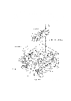
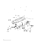
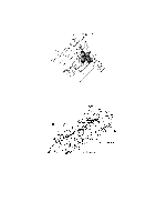
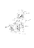
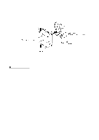
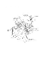
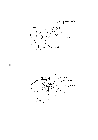
• When securing the lock plate R with screw "d," be sure to use the plastic jig as shown below to avoid damaging the edge of the FU lamp with a screwdriver. Lock plate R "d" FU lamp Plastic jig • A new heat-fixing unit will be provided with the heater thermistor harness being taped to the unit. Before installing the unit, remove the tape. • When setting the heat-fixing unit back into place, make sure that the heater wires are routed through the latch of the fan duct (see the illustration given on page IV-41) and then route the long heater wire as shown below. • If you remove and reinstall the heat-fixing unit because of any failure, make the machine enter the maintenance mode (see Note) after completion of reassembly and then make it exit from the mode (by pressing the 9 key twice). Otherwise, the heat-fixing unit may not become energized because of the following reason: If the failure of the heat-fixing unit is caused by an opening of the thermistor circuit (that senses the temperature of the heat-fixing unit), the system misinterprets the hot heater as being cold. As a result, the temperature of the heat-fixing unit may become excessively high. To prevent the system from heating the hot heater further at the next powering-on, it is designed so that the heater will not be energized. To cancel this setting, you need to carry out the above maintenance-mode procedure. (Note) Entry into the maintenance mode Machines w/ fax: Press the Function/Menu, *, 2, 8, 6, and 4 keys. Machines w/o fax: Press the Menu, 0, 2, 8, 6, and 4 keys. IV - 40
-
 1
1 -
2
-
3
-
4
-
5
-
6
-
7
-
8
-
9
-
10
-
11
-
12
-
13
-
14
-
15
-
16
-
17
-
18
-
19
-
20
-
21
-
22
-
23
-
24
-
25
-
26
-
27
-
28
-
29
-
30
-
31
-
32
-
33
-
34
-
35
-
36
-
37
-
38
-
39
-
40
-
41
-
42
-
43
-
44
-
45
-
46
-
47
-
48
-
49
-
50
-
51
-
52
-
53
-
54
-
55
-
56
-
57
-
58
-
59
-
60
-
61
-
62
-
63
-
64
-
65
-
66
-
67
-
68
-
69
-
70
-
71
-
72
-
73
-
74
-
75
-
76
-
77
-
78
-
79
-
80
-
 81
81 -
 82
82 -
 83
83 -
 84
84 -
 85
85 -
 86
86 -
 87
87 -
 88
88 -
 89
89 -
 90
90 -
 91
91 -
92
-
93
-
94
-
95
-
96
-
97
-
98
-
99
-
100
-
101
-
102
-
103
-
104
-
105
-
106
-
107
-
108
-
109
-
110
-
111
-
112
-
113
-
114
-
115
-
116
-
117
-
118
-
119
-
120
-
121
-
122
-
123
-
124
-
125
-
126
-
127
-
128
-
129
-
130
-
131
-
132
-
133
-
134
-
135
-
136
-
137
-
138
-
139
-
140
-
141
-
142
-
143
-
144
-
145
-
146
-
147
-
148
-
149
-
150
-
151
-
152
-
153
-
154
-
155
-
156
-
157
-
158
-
159
-
160
-
161
-
162
-
163
-
164
-
165
-
166
-
167
-
168
-
169
-
170
-
171
-
172
-
173
-
174
-
175
-
176
-
177
-
178
-
179
-
180
-
181
-
182
-
183
-
184
-
185
-
186
-
187
-
188
-
189
-
190
-
191
-
192
-
193
-
194
-
195
-
196
-
197
-
198
-
199
-
200
-
201
-
202
-
203
-
204
-
205
-
206
-
207
-
208
-
209
-
210
-
211
-
212
-
213
-
214
-
215
-
216
-
217
-
218
-
219
-
220
-
221
-
222
-
223
-
224
-
225
-
226
-
227
-
228
-
229
-
230
-
231
-
232
-
233
-
234
-
235
-
236
-
237
-
238
-
239
-
240
-
241
-
242
-
243
-
244
-
245
-
246
-
247
-
248
-
249
-
250
-
251
-
252
-
253
-
254
-
255
-
256
-
257
-
258
-
259
-
260
-
261
-
262
-
263
-
264
-
265
-
266
-
267
-
268
-
269
-
270
-
271
-
272
-
273
-
274
-
275
-
276
-
277
-
278
-
279
-
280
-
281
-
282
-
283
-
284
-
285
-
286
 |
 |
