Campbell Scientific TDR100 TDR100 Time Domain Reflectometry Systems - Page 20
SDM Communication
 |
View all Campbell Scientific TDR100 manuals
Add to My Manuals
Save this manual to your list of manuals |
Page 20 highlights
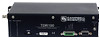
TDR100 components in the enclosure. A short run of heavy gage (10 AWG or heavier) wire should be connected from the enclosure lug to earth ground. The ground lug on peripheral SDMX50 multiplexer enclosures should only be used if the multiplexer is close enough to conveniently use the same ground point as the datalogger. 5.6 SDM Communication 5.6.1 SDM Addressing for TDR100 System SDM (Synchronous Device for Measurement) communication protocol is used with the TDR100, SDMX50 and Campbell Scientific dataloggers to control measurements and transfer data. On our CR800, CR850, CR1000, CR10X, and CR23X dataloggers, the ports labelled C1, C2, and C3 are dedicated to SDM functions DATA, CLOCK and ENABLE, respectively. On our CR3000, the ports are labelled SDM-C1, SDM-C2, and SDM-C3. The use of synchronous communications requires adherence to an addressing scheme for all communicating devices. SDM cables have 5 conductors. The red and black wires are typically used for 12 volt and ground. The remaining 3 wires connect the control lines. One is used to connect C1 or SDM-C1 of the datalogger to C1 of each of the other components of the system, e.g. TDR100 and SDMX50 multiplexer. Another wire is used to connect C2 or SDM-C2 of the datalogger to C2 of the other system components. The last wire is used to connect C3 or SDM-C3 of the datalogger to C3 of the other system components. If PCTDR is being used to control multiplexers, the control lines connect C1, C2 and C3 of TDR100 and multiplexer(s). The SDM address of the TDR100 is set using the thumbwheel switch on the TDR100 front panel. The address selected on the TDR100 must match the SDM Address used in the datalogger program. There are a maximum of three multiplexer levels (see Figure 5-1). The level 1 multiplexer has an address value equal to the TDR100 address plus 1. Level 2 multiplexers have an address value equal to the TDR100 address plus 2 and the level 3 multiplexers have an address value equal to the TDR100 address plus 3. Addressing for SDMX50 multiplexers with serial number 5238 and higher is set using the thumbwheel switch at the top of the panel. Addressing for SDMX50 multiplexers with serial number 5237 and lower is set with hardware jumpers. Changing the SDMX50 jumpers requires removing the multiplexer front cover. Figure 5-4 shows the location of jumpers used for SDMX50 addressing. Table 5-1 lists Edlog addresses (base 4) and jumper positions associated with them. It is recommended to use a TDR100 address of 0, level 1 SDMX50 address of 01, level 2 SDMX50 address of 02, and level 3 SDMX50 address of 03. 14
-
 1
1 -
2
-
3
-
4
-
5
-
6
-
7
-
8
-
9
-
10
-
11
-
12
-
13
-
14
-
 15
15 -
 16
16 -
 17
17 -
 18
18 -
 19
19 -
 20
20 -
 21
21 -
 22
22 -
 23
23 -
 24
24 -
 25
25 -
26
-
27
-
28
-
29
-
30
-
31
-
32
-
33
-
34
-
35
-
36
-
37
-
38
-
39
-
40
-
41
-
42
-
43
-
44
-
45
-
46
-
47
-
48
-
49
-
50
-
51
-
52
-
53
-
54
-
55
-
56
-
57
-
58
-
59
-
60
 |
 |
