Canon DR 7090C Reference Guide - Page 20
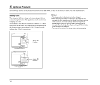
Rear, Air Vents, USB Connector, DIP Switches, Power Cord Connector
 |
UPC - 013803100242
View all Canon DR 7090C manuals
Add to My Manuals
Save this manual to your list of manuals |
Page 20 highlights
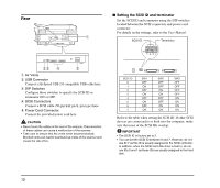
Rear ■ Setting the SCSI ID and terminator Set the SCSI ID and terminator using the DIP switches located between the SCSI connectors and power cord connector. For details on the settings, refer to the User Manual. SCSI ID Terminator 1 2 3 4 a Air Vents b USB Connector Connect a Hi-Speed USB 2.0 compatible USB cable here. c DIP Switches Configure these switches to specify the SCSI ID or terminator ON or OFF. d SCSI Connectors Connect a SCSI cable (50-pin half pitch, pin type) here. e Power Cord Connector Connect the provided power cord here. CAUTION • Never touch the cables at the rear of the scanner. Disconnection of these cables can cause a malfunction of the scanner. • Take care to ensure that the vents never become blocked. Blocked vents can lead to heat build-up inside of the scanner and create the risk of fire. SCSI ID 0 1 2 3 4 5 6 7 SW1 OFF ON OFF ON OFF ON OFF ON SW2 OFF OFF ON ON OFF OFF ON ON SW3 OFF OFF OFF OFF ON ON ON ON Refer to the table when setting the SCSI ID. If other SCSI devices are connected to or built into the computer, make sure that none of the SCSI IDs overlap. IMPORTANT • The SCSI ID is factory set to 2. • You can set the SCSI ID between 0 and 7. However, do not use ID 7 as this ID is usually assigned to the SCSI controller. In addition, when the SCSI hard disk drive is built in, do not use IDs 0 and 1 as these IDs are usually assigned to the hard disk. 12
-
 1
1 -
2
-
3
-
4
-
5
-
6
-
7
-
8
-
9
-
10
-
11
-
12
-
13
-
14
-
 15
15 -
 16
16 -
 17
17 -
 18
18 -
 19
19 -
 20
20 -
 21
21 -
 22
22 -
 23
23 -
 24
24 -
 25
25 -
26
-
27
-
28
-
29
-
30
-
31
-
32
-
33
-
34
-
35
-
36
-
37
-
38
-
39
-
40
-
41
-
42
-
43
-
44
-
45
-
46
-
47
-
48
-
49
-
50
-
51
-
52
-
53
-
54
-
55
-
56
-
57
-
58
-
59
-
60
-
61
-
62
-
63
-
64
-
65
-
66
-
67
-
68
-
69
-
70
-
71
-
72
-
73
-
74
-
75
-
76
-
77
 |
 |
