Canon PIXMA iP5000 iP5000 Easy Setup Instructions - Page 1
Canon PIXMA iP5000 Manual
 |
View all Canon PIXMA iP5000 manuals
Add to My Manuals
Save this manual to your list of manuals |
Page 1 highlights
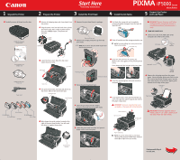
1 Unpack the Printer 2 Prepare the Printer Start Here Easy Setup Instructions 3 Install the Print Head 4 Install the Ink Tanks Series Photo Printer 5 Connect the Printer and Load Paper 1 Carefully remove all items from the box. PIXMA iP5000 Series Photo Printer Photo Printer Series Quick Start Guide 1 Remove all shipping tape and clear plastic from the printer. 2 Plug the power cord into the back of the printer and connect the other end to a power outlet. Press the POWER button. The printer will initialize. 1 Remove the print head from its package. POWER Button POWER Lamp Tear at notch to open 2 Remove the orange protective cap from the print head. NOTE: Do not touch the print head nozzles and the electrical contacts. 1 Peel back the orange tab and completely remove the plastic wrapper from the Cyan Ink Tank (BCI-6C). 2 Twist off and discard the orange protective cap. NOTE: To avoid spilling ink, never press on the sides of an ink tank. Protective Cap IMPORTANT: Be sure the printer is off before continuing, or the computer will attempt to install the printer driver before the printer is ready. 1 TURN THE PRINTER OFF. 2 Connect one end of the USB cable to the computer, the other to the printer. USB Cable USB Port Documentation and Software Kit PIXMA iP5000 Series Print Head Power Cord BCI-6Y Yellow BCI-6BK Black BCI-3eBK Black Ink Tanks BCI-6M Magenta BCI-6C Cyan 3 Lower the front cover. Raise the top cover. Lower the inner cover. Top Cover Inner Cover Print Head Nozzles Electrical Contacts Front Cover 3 Raise the print head lock lever. 4 The print head holder automatically moves to the center. Remove the protective tape. Protective Tape Serial Number 4 Slide the print head into the holder. The print head will rest at a slight angle. 5 Write down the serial number located to the right of the print head holder. You will need this later to register the product. 5 Lower the print head lock lever and press it down until it clicks into place. 3 Insert the ink tank into the correct slot. (Refer to the color guide on the print head lock lever.) Press down until the ink tank clicks into place. click 4 Insert the remaining four ink tanks into their assigned slots. 5 Close (a) the inner cover and then (b) the top cover. Lift open the paper support and extend the paper output tray. IMPORTANT: Be sure to close the inner cover completely, or the paper will not feed properly. Paper Support (a) Inner Cover (b) Top Cover Paper Output Tray NOTE: The printer will perform a print head cleaning. Wait until the POWER lamp displays a steady green light before proceeding. USB Cable USB Port 3 Remove the shipping tape from the paper guide. Pinch the paper guide and slide it to the left. Load a few sheets of blank paper into the auto sheet feeder, then slide the paper guide toward the left edge of the paper. Auto Sheet Feeder Paper Guide IMPORTANT: Print Head Alignment (Step 6) requires that 8.5" x 11" paper is loaded in the Auto Sheet Feeder (top paper feeder). Serial Number Location click Continue with Step 6 on side two.
-
 1
1 -
 2
2
 |
 |