Carvin RX1200L RX1200L Product Manual - Page 3
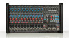
Rear Panel Features - mixer
 |
View all Carvin RX1200L manuals
Add to My Manuals
Save this manual to your list of manuals |
Page 3 highlights
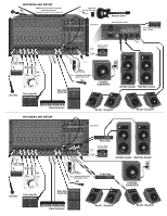
19. SUB X-OVER SWITCH The SUB XOVER (crossover) switch removes all frequencies above 120Hz for connecting the MONO(SUB) output to an amplified subwoofer. This is a 3rd order (18db/oct.) filter. 20. phantom power switch and LED The Phantom PWR switch turns on the microphone phantom power in the channel XLR jacks. This power is used for supplying a voltage to condenser microphones. The LED indicates the phantom power is turned on. The phantom power will not damage conventional dynamic microphones. Note: Make sure the phantom power is switched off before connecting or disconnecting microphones to the mixer. 21. monitor 1&2 outputs The MONITOR 1 - 2 line outputs are the same signals that feed the internal MONITOR amps 3 & 4. Use these outputs for additional power amps or recording gear. red PEAK LEDs are flashing on the processors. Turn up the MAIN controls to add effects to the MAIN L/R OUTPUTS. The MON 1-2 levels control the amount of effects that go to the MONITOR outputs. EFFECT PARAMETERS Each of the four effects have variable parameters that are easily adjusted by the SELECT and the PARAMETER controls to get the desired effect. Each "Select" & "Parameter" is described below. Note: An audible noise will be heard while adjusting the effects. A) ECHO: Use SELECT to change the amount of regeneration (number of repeats). The PARAMETER control adjusts the delay time between the original signal and the echo. B) REVERB: Turn SELECT for the amount of presence (high frequencies) in the reverb. The PARAMETER control adjusts decay. C) CHORUS: Turn SELECT for the amount of reverb with your chorus. The PARAMETER control adjusts the depth. 25 13 12 lowered from this position, they boost or cut respectively a narrow frequency band. To reduce feedback in the low frequency range, try lowering one of the 80 or 160 Hz sliders. High frequency feedback is usually reduced by lowering one of the 2k or 6k Hz sliders. To help prevent feedback, the main speakers should be placed in front and away from the microphones. For tone enhancement you may want to raise the 80, 160 sliders for deeper bass or the 6k, 12k sliders for crisper highs. 26. power LED The blue POWER LED indicates when the mixer is powered on. 27. PROTECT LED The mixer may go into "PROTECT" mode, engaging relays to mute the speakers if: a) impedance is below 4 ohms on any amplifier, b) shorted speaker cables, or c) ventilation problems. If this LED comes on, shut the mixer off and check for cable problems, proper impedance and obstructed rear cooling vents. If you encounter an overheat problem, leave the mixer on allowing the fan to cool down the internal components. The mixer will auto-reset. 28. AMP CLIP LED's The AMP CLIP LEDs indicate when the internal power amps are starting to distort (clip). Reduce the MAIN L/R, MONITOR 1 or MONITOR 2 master volumes to prevent distortion. REAR PANEL features RX1200L 29. POWER CONNECTIONS The rear panel contains the power switch and AC power cable connection. 30 23 29 10 15 20 21 22. EFF SEND 1&2 JACKs The EFF SEND 1&2 jacks can send signals to external processors. These are the same signals sent to the internal EFFECT 1 and EFFECT 2 processors. 23. DSP EFFECTS PROCESSORS Two 24-Bit processors provide a host of great sounding effects including Flange, Reverb, Echo, & Chorus. The channel EFF 1 & eff 2 send controls deliver the signals to the dual processors. Note: Reduce these levels if the 11 27 26 14 16 17 18 19 28 24 22 D) FLANGE: Turn SELECT for the speed of your flange (phasing effect). The PARAMETER control adjusts depth. 24. EFFects FOOT SWitch JACK The optional FS22 will remotely shut off effects 1 or EFFECTS 2. 25. Adjusting THE GRAPHIC EQUALIZER When the EQ sliders are in their center position, they do not affect the audio signal. When EQ sliders are raised or 31 30. AMP PATCH INSERTS The AMP PATCH INSERT jacks offer full flexibility for mixer to amp signal routing. These jacks are T-R-S (Tip-Ring-Sleeve). Tip is the power amp input. Ring is the signal sent from the mixer. The builtin power amp limiters are post insert. Patching a compressor or equalizer between the mixer and the amp can be done by using a stereo insert cable (like Carvin's AP1). Connect the RING signal to the INPUT of the external device, and the TIP signal from the OUTPUT of the device. Plugging in a standard 1/4" cable (mono) into the AMP PATCH INSERT jacks allows any external signal to be sent to the internal power amps. ***DO NOT USE A BALANCED SIGNAL CABLE*** 31. SPEAKER CONNECTIONS For the RX1200L, there are 4 speaker jacks. These will accept either Twist-Lok (Speakon™) or 1/4" plugs. Amp 1 is for left speakers. Amp 2 is for RIGHt speakers. Amp 3 is for MonitoR 1 speakers. Amp 4 is for MonitoR 2 speakers. NOTE: 4 ohms MIN. IMPEDANCE PER AMPLIFIER (Maximum one 4 ohm or two 8 ohm speakers per amp).
-
 1
1 -
 2
2 -
 3
3 -
 4
4 -
 5
5
 |
 |
