Carvin XP1000L XP1000L Product Manual - Page 2
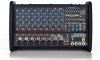
Xp1000l Controls - powered mixer
 |
View all Carvin XP1000L manuals
Add to My Manuals
Save this manual to your list of manuals |
Page 2 highlights
XP1000L CONTROLS Quick Start Up If you're like most new owners, you're probably in a hurry to plug your mixer in and use it. Here are some brief instructions to get you going quickly. With the mixer unplugged and the unit turned off, complete the following procedures: A. CONNECTING AC POWER TO YOUR MIXER • Start by plugging in your mixer. It will automatically select 120V-60Hz or 240V-50Hz. • Use only a grounded (3 prong) power outlet to prevent a shock hazard (do not bypass). This gives the quietest grounding for your mixer. B. CONNECTING INPUTS TO YOUR MIXER • For microphones, use a XLR shielded cable and plug into the XLR MIC inputs. • For high output devices like instruments & keyboards, plug into the LINE input jacks using a shielded cable. Adjust the channel GAIN control for mic or for instrument. C. TURNING YOUR MIXER ON • Set all Channel and Master LEVEL controls to their OFF positions. • Set all HI, MID, and LOW controls and the GRAPHIC EQUALIZERS to the center "flat - no boost or cut" position. • Adjust all "BAL" controls to their center position. • Connect your speakers and monitors at the rear panel. • Turn the mixer on by the rear POWER SWITCH and watch for the front POWER LED to come on. Your mixer is now ready to operate by gradually turning up the levels. post-channel level, which automatically tracks the channel's LEVEL & TONE controls. Turning this control to the left will send to the internal effects processor EFF1. Turning to the right will send to the internal effects processor EFF2 (and the external EFF 2 SND jack). Center "0" is off. Reduce these levels if the PK LEDs are flashing on the effects processors. 8. CHANNEL MONITOR CONTROL The MON control adjusts the volume of the channel going to the master MONITOR control. The MON control is a pre-LEVEL control. This means it is unaffected by the channel LEVEL. 9-11. CHANNEL TONE CONTROLS Each channel features active 3-band EQ tone controls LOW, MID, and HI. All three function as boost (clockwise) & cut (counter-clockwise) controls. The center 0 is the "flat" or no effect position. The LOW and HI controls are shelving type with corner frequencies at 80Hz and 11.5k Hz respectively. The MID control is a band pass type centered at 750Hz. Your settings will vary with the type of voice or instrument. Try reducing the MID to add clarity and turn up the LOW and 11 10 15. TAPE OUT LEVEL The TAPE OUT LEVEL sends the MAIN signal mix to the TAPE OUT jacks for recording. The TAPE OUT level is unaffected by the MAIN level control so a recording level can be set independently of the MAIN speaker volume. 16. TAPE OUT JACKS Use the TAPE OUT L/R jacks for recording or to send to external power amps. If the TAPE OUT is being used to record, make sure the TAPE IN jacks are not connected to the recorder output or turn the channel 9/10 LEVEL to "0" or feedback will result. 17. EFF 2 SEND JACK The EFF 2 SEND jack can send a signal to an external processor. This is the same signal sent to the internal EFF 2 processor. Effect returns can be connected to any input channel. Make sure the EFF control for the return channel is set to "OFF" or "EFF1" or feedback will occur. 18. MAIN L-R OUTPUTS The MAIN L/R outputs are the same signals that feed the MIC CHANNEL FEATURES 9 1. XLR MICROPHONE INPUT The XLR MIC input is designed for balanced low impedance microphones. The high performance, low noise preamps do 8 a superb job of noise reduction. The XLR connector is wired as per the industry standard, pin 1 is ground, pin 2 is non- 7 inverting (positive), and pin 3 is inverting (negative). Note: Make sure the +48v phantom power is switched off before connecting or disconnecting microphones to the mixer. 6 2. LINE INPUT JACKS 5 The LINE input is a 1/4" phone jack designed for balanced or unbalanced line or instruments. Examples of these inputs would be guitar, keyboard or effect returns. The line input 4 can be used at the same time the mic input is being used. 3 Channels 7/8 and 9/10 feature stereo LINE INPUTS for stereo (use the top jack for mono input). 3. GAIN CONTROL (CHANNELS 1-6) 2 The GAIN control adjusts the input sensitivity on both the LINE and MIC input jacks over a range of 40dB. For quietest operation, set the GAIN control just below the point where 1 the PK LED flashes. If the PK LED lights or if distortion is heard, reduce the GAIN slightly until the PK LED is off. 4. CHANNEL "PK" LED The PK LED indicates when the channel is nearing its clipping level, causing distortion. Reduce the GAIN slightly to prevent distortion. On channels 7/8 and 9/10, reduce the level from your external souce. To get more volume, increase the master MAIN control and re-adjust your main mix. 5. CHANNEL LEVEL CONTROL The LEVEL control adjusts the volume of the channel before going to the BALANCE control. Here is where the individual channel volumes are adjusted to make up the desired mix at the main outputs. 6. CHANNEL BALANCE CONTROL The BAL control places the channel between Left and Right in the main stereo outputs. At the "0" center setting, the channel will be heard equally from the Left and Right outputs. When both 1/4" jacks are used on channels 7/8 or 9/10, the BAL adjusts the L-R levels, sending signals from LINE 7/9 to the LEFT, and signals from LINE 8/10 to the RIGHT. 7. CHANNEL EFFECTS 1&2 LEVEL The EFF 1&2 adjusts the level sent to the dual effects processor and to the front EFF SND 2 jack. The effects control is HI for a fuller sound. Channels 7/8 and 9/10 feature stereo TONE controls. 12. TAPE IN JACKS (CHANNEL 9/10) The L-R TAPE IN inputs on CHANNEL 9/10 are for connecting an iPod/MP3 or CD. These TAPE IN jacks can be used for returning another stereo effects processor or instrument (keyboard). Channel 9/10 inputs are NOT muted by the MUSIC BREAK switch allowing you to have background music while everything else is turned off. MASTER SECTION FEATURES 13. MAIN LEVEL (L & R AMPS) The MAIN control is the master volume control for all channels. The MAIN signal is sent through the MAIN L-R GRAPHIC EQ to the L and R amps and the front L/R output jacks which can be used for additional power amps, etc. 14. MONITOR LEVEL (MONITOR AMP) The MONITOR master level is sent through the MONITOR GRAPHIC EQ to the MONITOR amp and front output jack. internal LEFT and RIGHT amps. Use these balanced 1/4" outputs to feed additional power amps, etc.. 19. MONITOR OUTPUT The MONITOR output is the same signal that feeds the internal MONITOR amp. Use this balanced output to feed additional power amps, etc.. 20. DUAL EFFECT PROCESSORS Two 24-BIT processors provide a host of great sounding effects including Flange, Reverb, Echo, & Chorus. The channel EFF 1 & 2 send control delivers the signals to the processors. Note: Reduce these levels if the red PEAK LEDs are flashing at the processors. Turn up the MAIN EFFECTS control to add your effects to the L-R outputs. Adjust the SELECT and the PARAMETER to get the desired effect. Note: An audible noise will be heard while adjusting the effects. A) ECHO: Turn SELECT for the amount of regeneration (repeats). Now turn the PARAMETER control for a shorter or longer delay time between the original signal and the echo.
-
 1
1 -
 2
2 -
 3
3 -
 4
4
 |
 |
