Carvin XP800L XP800L Product Manual - Page 2
Carvin, Xp8ool - for guitar
 |
View all Carvin XP800L manuals
Add to My Manuals
Save this manual to your list of manuals |
Page 2 highlights
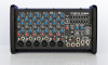
XP800L CONTROLS QUICK START UP If you're like most new owners, you're probably in a hurry to plug your mixer in and use it. Here are some brief instructions to get you going quickly. With the mixer unplugged and the unit turned off, complete the following procedures: A. CONNECTING AC POWER TO YOUR MIXER • Be sure to plug your mixer into the proper AC volt- age marked on the rear of your mixer. • Use only a grounded (3 prong) power outlet to prevent a shock hazard (do not bypass). This also gives the quietest grounding for your mixer. B. CONNECTING INPUTS TO YOUR MIXER • For balanced microphones, use a shielded cable and plug into the XLR MIC inputs. • For high output devices like instruments & key- boards, plug into the LINE input jacks using a shielded cable. • Set the MIC IN switch "OUT" for instruments or "IN" for microphones. C. TURNING YOUR MIXER ON • Set all channel and master LEVEL controls to their OFF positions • Set all HI, MID, and BASS controls and the graphic equalizers to their center "flat" (no boost or cut) position. • Connect your speakers at the front panel. • Turn the mixer on by the rear POWER switch and watch for the front POWER LED to come on. Your mixer is now ready to operate. 4, 10 1 HI -.0+ 3 6 6 MID 3-0+3 912 9 12 HI AL 3-0+ 6 MID 912 129 3_0+3 HI 3-0+3 MID 9 9 3_0+3 12 12 4 HI 3-a+ 3 6 i 6 MID 9 9 3. 0+3 12 12 STEREO 5/6 HI 3-0+ 6 l6 MID 9 9 3 _0+3 12 12 STEREO 7/8 HI 3-0+ 3 . MID 3 _0+3 912 12 0K1R, POWE CARVIN XP8OOL MAIN L/R OR MAIN/MONITOR 1 +12 18 6 6 6(1) 6 6 6 6 6 6 6 6 MAIN L/R 1•2- 12 9 LOW 3 _0+3 • 9 LOW 912 12 3 _0+3 6 6 6 6 LOW 9 12 3-0+3 1Z 6 6 LOW 9 12 3 _0+3 12 6 6 LOW 9 12 3 _0+3 12 6 6 .19 LOW 12 _0+ 33 (AMPS 1&2) LIJ 6 6 MAIN / MONI • -12 I - = -12 MON 9 9 4 5 6 12- 12 MON 9 9 4 5 6 1,-z 12 MON 9 9 4 5 6 12 12 MON 9 9 4 5 6 12 12 MON 9 4 5 6 3 7 30 7 30 7 3 7 3 7 MON 9 1 9 (AMP1/AMP 12 4 3 5 67 2 2 MAIN MONITOR EFFECTS EFFECTS TO MAIN TO MONITOR 19 CD 2 8 2 8 2 8 2 h. 8 .-R 2 8 2 109 EFF 1 io9 EFF 1 09 EFF 1 og EFF 1 O9 EFF 56 3. 7 4 5 67 3 34 5 6 7 4 5 6 3 7 5 34 67 8 09 EFF 344c 5 *6,?. 4 5 6 3 7 2 8 10 _it 4 5 6 3 7, 2 8 . .5. • • • • • 0 "4 •.50• • • • 0 EFFECTS SELECT & ADJUST ECHO REGEN / TIME 8 2 8 2 8 2 , 8 2 8 2 8 LEVEL 4\0 4 5 6 1' 09 LEVEL 1 4 5 67 109 LEVEL 1 4 5 6 10 LEVEL 10 4 5 6 11 0 9 LEVEL 1 4 5 6 109 LEVEL 4 5 6 10 AO 3/7 3 3 0,74 3 7 3 Ilip\7 3 7 2 8 2 8 2 8 2 8 2 8 2 8 USB POWER 24-BIT •TEREO EFF CTS SEL CT ADJ tOc cts. 4" et„ ••. 5 •• CHORUS REV LEVEL/DEPTH FLANGE SPEED/DEPTH 16 9 1V 9 1y_ 1 ° LINE 10 LINE 109 LINE 9 0 LINE 1 )9 L 04,2 LINE 1 0 )9 MIC IN MIC IN MIC IN MIC IN R L R ANTOM OWED 48V T.3> TAPE OUT LEFT if.> RIGH 4) • 0 SPEAKERS 21 +20d +20dB I i +20dB +20dB 0 • 0 MIC MIC 5/6 MIC MIC LEFT RIGHT (MAIN) t i(MONITOR)t i LEFT OUT RIGHT OUT MON OUT O Iw di • • • • • • to • AMP1 4 OHM MIN AMP2 4 OHM MIN 11 2 13 15 14 MIC CHANNEL FEATURES MASTER SECTION FEATURES 1. XLR MICROPHONE INPUT The XLR MIC input is designed for balanced low impedance microphones. The high performance, low noise preamps do a superb job of noise reduction. The XLR connector is wired as per the industry standard, pin 1 is ground, pin 2 is non-inverting (positive), and pin 3 is inverting (negative). Note: Make sure the phantom power is switched off before connecting or disconnecting microphones to the mixer. 2. LINE INPUT JACKS (CH 1-4) The LINE input is a 1/4" phone jack designed for balanced or unbalanced line or instruments. Examples of these inputs would be guitar, keyboard or effect returns. The line input can be used at the same time the mic input is being used. 3. STEREO L/R LINE IN JACKS (CH 5-8) The LINE L and LINER inputs on CHANNEL 5/6 and 7/8 are for connecting a MP3, CD or tape player. These RCA jacks can also be used for returning another effects processor or instrument (keyboard) 4. MIC IN +20DB GAIN SWITCH (CH 1-4) The +20DB switch increases the input sensitivity on both the LINE and MIC input jacks by 20dB. After determining the input is too low for mixing with the level control, turn down the level control, press in the gain switch and adjust the level again. If distortion is heard regardless of the channel LEVEL control's setting, disengage this switch to eliminate over-driving of the input stage. 5. CHANNEL LEVEL CONTROL The LEVEL control adjusts the volume of the channel before going to the MAIN level control. Here is where the individual channel volumes are adjusted to make up the desired mix at the main outputs. 6. CHANNEL EFFECTS LEVEL The EFF control adjusts the level sent to the effects processor and to the front EFF SND jack. The effects control is post-channel level, which automatically tracks the channel's LEVEL & EQ controls. Reduce the EFF level if the PK LED is flashing near the main effects processor controls. 7. CHANNEL MONITOR CONTROL The MON control adjusts the volume of the channel going to the master MONITOR control. The MON control is a m -LEVEL control. This means it is unaffected by the channel LEVEL. 8-10. CHANNEL TONE CONTROLS Each channel features active 3-band EQ tone controls LO, MID, and HI. All three function as boost (clockwise) & cut (counter-clockwise) controls. The center 0 is the "flat" or no effect position. The LO and HI controls are shelving type with corner frequencies at 80Hz and 11.5k Hz respectively. The MID control is a band pass type centered at 750Hz. These settings will vary with the type of voice or instrument. Try reducing the MID to add clarity and turn up the LO and HI for a fuller sound. 11. MAIN LEVEL The MAIN control is the master volume control for all channels. The MAIN stereo L/R signals are sent to the front LEFT OUT and RIGHT OUT jacks, and through the GRAPHIC EQ to AMP1 and AMP2 front speaker outputs (with the MAIN/MONITOR switch "IN", a combined MONO signal is sent to AMP1 only) 12. MONITOR LEVEL The MONITOR signal is sent to front MON OUT jack, and with the MAIN/MONITOR switch "IN", is sent through the GRAPHIC EQ to AMP2. 13. MAIN LEFT/RIGHT OUTPUTS The front LEFT OUT and RIGHT OUT are the same stereo signals that feeds the internal amps, but without the Graphic EQ. Use these 1/4" outputs to feed additional power amps, etc.. 14. MONITOR OUTPUT The front MON OUT is the same signal that feeds the internal amp, but without the Graphic EQ. Use this 1/4" output to feed additional power amps, in ear monitors, etc.. 15. TAPE OUT JACKS Use the TAPE OUT L-R jacks for recording or to send to external power amps. If the TAPE OUT is being used to record, make sure the TAPE IN jacks are not connected to the recorder output or turn the channel LEVEL to "0" or feedback will result. 16. DSP EFFECTS PROCESSOR EFFECTS EFFECTS TO NADI TO MONITOR t' ISELECTEADJUST _.4 *0 24-BR STEREO EFFECTS 00t0m. WiIN SELECT ADJUST MOMS • A 24-Bit processor provides a host of great sounding effects including Echo, Reverb, Chorus, and Flange. The channel EFF send control delivers the signals to the processor. Note: Reduce these levels if the red PEAK LED is flashing near the main processor controls. Turn up the EFFECTS TO MAIN control to add effects to the MAIN LEFT and RIGHT outputs. Turn up the EFFECTS TO MONITOR control to add effects to the MONITOR outputs. Adjust the SELECT and the PARAMETER controls to get the desired effect. Note: An audible noise will be heard while adjusting the effects. A) ECHO: Turn SELECT for the amount of regeneration (repeats). Now turn the PARAMETER control for a shorter or longer delay time between the original signal and the echo. B) REVERB: Turn SELECT for the amount of presence (high frequencies) in the reverb. Now turn the PARAMETER control to change the decay time of the reverb. C) CHORUS: Turn SELECT for the amount of reverb with your chorus. Now turn the PARAMETER control to change the chorus depth. D) FLANGE: Turn SELECT for the speed of your flange (phasing effect). Now turn the PARAMETER control to change the flange depth. 17. EFF SEND JACK The EFF SEND jack can send a signal to an external processor. This is the same signal sent to the internal effects processor. Effect returns can be connected to any input channel. Make sure the EFF control for the return channel is set to "0" or feedback will occur. 18. POWER LED The blue POWER LED indicates the mixer is powered ON. 19. MAIN/MONITOR SWITCH - AMP ASSIGN With the switch "IN" , AMP 1 is for MAIN (mono), and AMP 2 is for MONITOR. With the switch "OUT", AMP1 and AMP2 are in stereo for the MAIN LEFT and RIGHT speakers. The front MON OUT jack is unchanged by the switch setting and can be used for external power amps or in-ear monitor systems. 20. STEREO GRAPHIC EQ When the EQ sliders are in their center position, they do not affect the audio signal. When EQ sliders are raised or lowered from this position, they boost or cut a narrow frequency band. For tone enhancement you may want to raise the 80Hz and 160Hz sliders (for deeper bass) and the 6kHz and 12kHz sliders (for crisper highs) while reducing the 400Hz, 800Hz and 2kHz sliders in a moderate "curve". To help prevent feedback, microphones should be placed behind the main speakers. To reduce feedback in the low frequency range, try lowering one of the 80Hz or 160Hz sliders. High frequency feedback is usually reduced by lowering the 2kHz or 6kHz sliders. 21. USB POWER PORT The USB POWER PORT allows charging of an iPodTM/ MP3 player, or to power accessories such as LED lighting. Connect audio outputs from devices to the LINE L-R inputs on channels 5/6 or 7/8. USB POWER C- ) 22. 48V PHANTOM POWER SWITCH / LED The 48V PHANTOM POWER switch turns on the microphone phantom power in the channel XLR jacks. This power is used for supplying a high voltage to condenser microphones. The LED indicates the phantom power is turned on. The phantom power will not damage conventional dynamic microphones. Note: Make sure the phantom power is switched off before connecting or disconnecting microphones to avoid a "pop". 23. SPEAKER OUTPUTS Each amp has a 4ohms MINIMUM IMPEDANCE (Maximum TWO 8ohms speakers, OR ONE 4ohms speaker per AMP output jack). MAKE ALL CONNECTIONS BEFORE TURNING THE MIXER ON. SPEAKERS LEFT RIGHT (MAIN) I I (MONITORI)tiir AMP1 AMP2 4 OHM MIN 4 OHM MIN REAR PANEL FEATURES: POWER SWITCH AND AC CONNECTOR The rear panel contains the POWER SWITCH and AC power cable connection.
-
 1
1 -
 2
2
 |
 |
