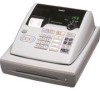
Casio PCRT275 Owners Manual - Page 8
Removing the main PCB, Disassembling the keyboard unit
 |
View all Casio PCRT275 manuals
Add to My Manuals
Save this manual to your list of manuals |
Page 8 highlights
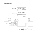
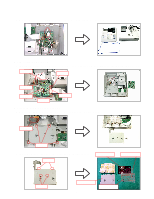
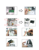
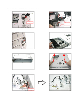
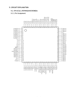
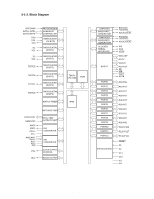
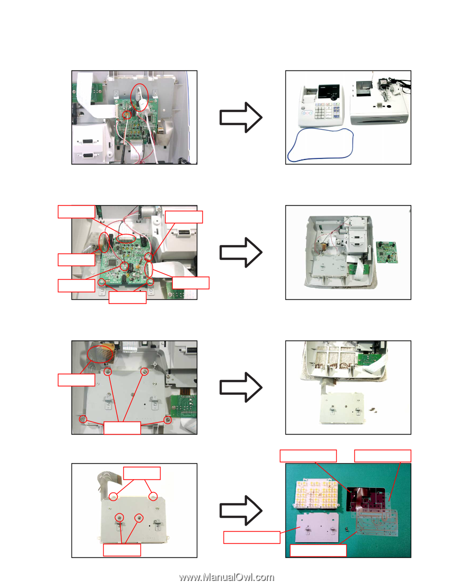
5. Remove the connector (CN7) as well as the power jack, and then separate the main unit from the drawer. s Removing the main PCB 6. Remove the connectors (CN6, CN8), FPCs(CN1, CN3, CN9) and the two screws and then remove the main PCB. CN1 CN6 CN3 CN8 Screws CN9 s Disassembling the keyboard unit 7. Remove the FPC as well as the four screws, and then the keyboard unit. FPC Screws 8. Remove the two screws and then disassemble the keyboard unit. Hooks Spacer Common sheet Screws Chassis - 6 - FPC
-
 1
1 -
2
-
 3
3 -
 4
4 -
 5
5 -
 6
6 -
 7
7 -
 8
8 -
 9
9 -
 10
10 -
 11
11 -
 12
12 -
 13
13 -
14
-
15
-
16
-
17
-
18
-
19
-
20
-
21
-
22
-
23
-
24
-
25
-
26
-
27
-
28
-
29
-
30
-
31
-
32
-
33
-
34
-
35
-
36
-
37
-
38
-
39
-
40
-
41
-
42
-
43
-
44
-
45
-
46
-
47
 |
 |
— 6 —
5. Remove the connector (CN7) as well as the power jack, and then separate the main unit from the drawer.
■
Removing the main PCB
6.
Remove the connectors (CN6, CN8), FPCs(CN1, CN3, CN9) and the two screws and then remove the main PCB.
CN9
CN8
CN6
CN3
CN1
Screws
■
Disassembling the keyboard unit
7. Remove the FPC as well as the four screws, and then the keyboard unit.
8. Remove the two screws and then disassemble the keyboard unit.
Screws
FPC
Screws
Hooks
Chassis
FPC
Spacer
Common sheet