Celestron CGE Pro 925 Computerized Telescope CGE Pro Series Manual - Page 8
One Person Installation, Adjusting the Latitude Plate
 |
View all Celestron CGE Pro 925 Computerized Telescope manuals
Add to My Manuals
Save this manual to your list of manuals |
Page 8 highlights
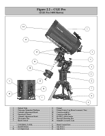
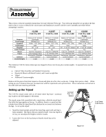
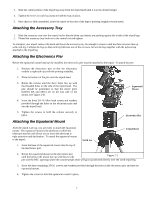
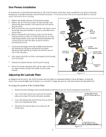
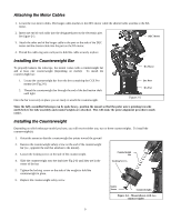
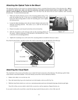
One Person Installation As an alternative to the method described above, The CGE Pro mount can be more easily assembled by one person if the polar housing axis is installed separately from the latitude side plates. To do this you must first lay the equatorial head on a flat soft surface and remove the two sections. 1. Remove the latitude indicator from the polar housing. 2. Remove the two bolts that connect the polar housing to the latitude side plate assembly, and loosen (but do remove) the two pivot bolts. 3. With the electronics pier securely attached to the tripod, mount the latitude side plate assembly to the pier as described in the section above. 4. Before mounting the polar housing, make sure that the RA locking clutches are secure so that the housing can not rotate while being installed. Also rotate the latitude adjustment bolt counterclockwise until only about an inch of thread is protruding downward. Latitude Indicator Polar Housing Section Pivot Bolts 5. Lift the polar housing section and carefully lower the polar axis between the side plates (and beneath the latitude adjustment bolt) until the pivot bolts rest inside the two cut outs on the side plates. 6. Once seated, attach the two bolts connecting the polar housing to the side plates. Cutouts for Pivot Bolts Latitude Adjustment Bolt Latitude Side Plate Assembly 7. Reattach the latitude indicator from the polar housing. 8. Rotate the latitude adjustment bolt until the angle of the polar axis approximately matches the latitude of your current location. Adjusting the Latitude Plate Figure 2-3 Attachment Bolts As shipped from the factory, the CGE Pro mount will only adjust to a maximum latitude of about 40 degrees. If using the mount from a latitude higher than 40 degrees you will need to change the position of the latitude plate and adjustment bolt. To change the position of the Latitude Plate: 1. Remove the polar housing section from the mount as described in the One Person Installation section above. 2. Use a 5mm Allen wrench to remove the four latitude plate screws (fig 2-4) from the side plate assembly. Latitude Plate Screws - For 40° latitude and lower 3. Lower the latitude plate until the holes line up with the lower set of latitude plate holes. 4. Thread the four latitude plate screws back into the latitude plate. Latitude Plate Screws - For 40° latitude and higher Figure 2-4 8
-
 1
1 -
2
-
 3
3 -
 4
4 -
 5
5 -
 6
6 -
 7
7 -
 8
8 -
 9
9 -
 10
10 -
 11
11 -
 12
12 -
 13
13 -
14
-
15
-
16
-
17
-
18
-
19
-
20
-
21
-
22
-
23
-
24
-
25
-
26
-
27
-
28
-
29
-
30
-
31
-
32
-
33
-
34
-
35
-
36
-
37
-
38
-
39
-
40
-
41
-
42
-
43
-
44
-
45
-
46
-
47
-
48
-
49
-
50
-
51
-
52
-
53
-
54
-
55
-
56
-
57
-
58
-
59
-
60
-
61
-
62
-
63
-
64
-
65
-
66
-
67
-
68
-
69
-
70
-
71
-
72
 |
 |
