Cisco 1751V Hardware Installation Guide
Cisco 1751V Manual
 |
UPC - 746320568683
View all Cisco 1751V manuals
Add to My Manuals
Save this manual to your list of manuals |
Cisco 1751V manual content summary:
- Cisco 1751V | Hardware Installation Guide - Page 1
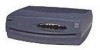
Cisco 1751 Router Hardware Installation Guide Corporate Headquarters Cisco Systems, Inc. 170 West Tasman Drive San Jose, CA 95134-1706 USA http://www.cisco.com Tel: 408 526-4000 800 553-NETS (6387) Fax: 408 526-4100 Customer Order Number: DOC-7811258= Text Part Number: 78-11258-04 - Cisco 1751V | Hardware Installation Guide - Page 2
is for FCC compliance of Class B devices: The equipment described in this manual generates and may radiate radio-frequency energy. If it is not installed in accordance with Cisco's installation instructions, it may cause interference with radio and television reception. This equipment has been - Cisco 1751V | Hardware Installation Guide - Page 3
in this document or Website are the property of their respective owners. The use of the word partner does not imply a partnership relationship between Cisco and any other company. (0501R) Cisco 1751 Router Hardware Installation Guide Copyright © 2005 Cisco Systems, Inc. All rights reserved. - Cisco 1751V | Hardware Installation Guide - Page 4
- Cisco 1751V | Hardware Installation Guide - Page 5
About This Guide ix Audience and Scope x Organization x Related Publications xi Conventions xi Notes, Cautions, and Warnings xi Commands xiv Cisco 1751 Router Overview 1-1 Key Features 1-2 Rear-Panel Ports and LEDs 1-4 Front-Panel LEDs 1-6 Router Memory 1-9 Types of Memory 1-9 Amounts of Memory 1-10 - Cisco 1751V | Hardware Installation Guide - Page 6
3-11 Troubleshooting ISDN 3-12 Fan Behavior 3-14 Technical Specifications A-1 Cabling Specifications B-1 Ethernet Cables B-1 Ethernet Network Cabling Guidelines B-2 Console Cable and Adapters B-3 VIC Cables and Pinouts B-5 Cables and Pinouts for 2-Port ISDN BRI Card B-7 Cisco 1751 Router Hardware - Cisco 1751V | Hardware Installation Guide - Page 7
1751 Chassis A-9 Installing the Echo Canceler Expansion Modules on Cisco Interface Cards E-1 Multiflex Trunk Interface Cards E-1 Echo E-2 Echo Canceler Expansion Modules E-2 Installing and Configuring the Echo Canceler Expansion Modules E-3 78-11258-04 Cisco 1751 Router Hardware Installation Guide - Cisco 1751V | Hardware Installation Guide - Page 8
Contents Cisco 1751 Router Hardware Installation Guide viii 78-11258-04 - Cisco 1751V | Hardware Installation Guide - Page 9
of the Cisco 1751 Router Hardware Installation Guide and defines the conventions used to convey instructions and information. You can access Cisco documentation and additional literature on the World Wide Web at http://www.cisco.com, http://www-china.cisco.com, or http://www-europe.cisco.com. If - Cisco 1751V | Hardware Installation Guide - Page 10
guide is organized as follows: • Chapter 1, "Cisco 1751 Router Overview," describes the router features, front-panel LEDs, rear-panel LEDs, and connectors. • Chapter 2, "Installation," describes how to install the router by connecting cables, power, and install WAN interface cards (WICs) and voice - Cisco 1751V | Hardware Installation Guide - Page 11
IOS command-line interface (CLI) to configure the router in these scenarios. • Cisco 1751 Router Software Configuration Guide provides instructions on how to use Cisco IOS software to configure voice interfaces and virtual LANs (VLANs). • Cisco 1- and 2-port T1/E1 Multiflex Voice/WAN Interface Cards - Cisco 1751V | Hardware Installation Guide - Page 12
Conventions About This Guide Caution This caution symbol means reader be careful. In this situation, you might do Compliance and Safety Information (Conformité aux règlements et consignes de sécurité) qui accompagne cet appareil. Cisco 1751 Router Hardware Installation Guide xii 78-11258-04 - Cisco 1751V | Hardware Installation Guide - Page 13
About This Guide Conventions Warnung Avvertenza Advarsel Aviso Dieses Warnsymbol bedeutet Gefahr. Sie befinden sich in einer Situation, Information (Informação de Segurança e Disposições Reguladoras) que acompanha este dispositivo. 78-11258-04 Cisco 1751 Router Hardware Installation Guide xiii - Cisco 1751V | Hardware Installation Guide - Page 14
Commands Table 1 describes the syntax used with the commands in this document. Table 1 Command Syntax Guide Convention Description boldface Commands and keywords. italic Command font Examples of information that you must enter. Cisco 1751 Router Hardware Installation Guide xiv 78-11258-04 - Cisco 1751V | Hardware Installation Guide - Page 15
About This Guide Conventions Table 1 Command Syntax Guide Convention [] Description Nonprinting characters, such as passwords, appear in angled brackets. Default responses to system prompts appear in square brackets. 78-11258-04 Cisco 1751 Router Hardware Installation Guide xv - Cisco 1751V | Hardware Installation Guide - Page 16
Conventions About This Guide Cisco 1751 Router Hardware Installation Guide xvi 78-11258-04 - Cisco 1751V | Hardware Installation Guide - Page 17
the Cisco 1751 router, also referred to in this guide as the router, and covers the following topics: • Key Features • Rear-Panel Ports and LEDs • Front-Panel LEDs • Router Memory • Unpacking the Router • Additional Required Equipment Figure 1-1 shows the Cisco 1751 router. 78-11258-04 Cisco 1751 - Cisco 1751V | Hardware Installation Guide - Page 18
Key Features The Cisco 1751 router is a voice-and-data capable router that provides Voice-over-IP functionality (VoIP) and can carry voice traffic (for example, telephone calls and faxes) over an IP network. Using one to four WAN connections, the router links small-to-medium-size remote Ethernet and - Cisco 1751V | Hardware Installation Guide - Page 19
Management Protocol (SNMP) to manage the router over a network. Supports Voice over IP, Voice over Frame Relay, and Voice over ATM connections. Supports AutoInstall to download configuration files to the router over a WAN connection. 78-11258-04 Cisco 1751 Router Hardware Installation Guide 1-3 - Cisco 1751V | Hardware Installation Guide - Page 20
configure a network that includes the Cisco 1751 router. Supports Cisco Voice Manager to help you install and operate voice and fax services over the IP network. Stackable with other Cisco Networked Office stack products. Rear-Panel Ports and LEDs This section describes the router rear-panel ports - Cisco 1751V | Hardware Installation Guide - Page 21
configuration using Cisco IOS software. Supports either a Cisco WIC or VIC. For detailed information, refer to the Cisco WAN Interface Cards Hardware Installation Guide that comes with every card. Supports either a Cisco WIC or VIC. For detailed information, refer to the Cisco WAN Interface Cards - Cisco 1751V | Hardware Installation Guide - Page 22
slot. Green On when a packet voice data module (PVDM) is correctly inserted in the card slot. Green On when a VPN module is present. Front-Panel LEDs Use the router front-panel LEDs to determine network activity and status on the Ethernet port and on the WIC and VIC ports. The front-panel LEDs are - Cisco 1751V | Hardware Installation Guide - Page 23
the local Ethernet network. On when the first ISDN B channel is connected. Blinks when data is being sent to or received from the port. For the VIC-2BRI-ST-NT/TE, blinks when data is being sent to or received from any of the B channels. 78-11258-04 Cisco 1751 Router Hardware Installation Guide 1-7 - Cisco 1751V | Hardware Installation Guide - Page 24
from the port. On when the first ISDN B channel is connected. Blinks when data is being sent to or received from the port. Off. On when the first ISDN B channel is connected. Blinks when data is being sent to or received from the port. Cisco 1751 Router Hardware Installation Guide 1-8 78-11258 - Cisco 1751V | Hardware Installation Guide - Page 25
copy of Cisco IOS software, dynamic configuration information, and routing table information in DRAM. The Cisco 1751 router ships with 32 MB of DRAM. • Nonvolatile RAM (NVRAM)-This type of memory contains the startup configuration. 78-11258-04 Cisco 1751 Router Hardware Installation Guide 1-9 - Cisco 1751V | Hardware Installation Guide - Page 26
3.0.0. 1 FastEthernet/IEEE 802.3 interface(s) 2 ATM network interface(s) 2 Voice FXS interface(s) 32K bytes of non-volatile configuration memory. 32768K bytes of processor board System flash (Read/Write) Configuration register is 0x0 1-10 Cisco 1751 Router Hardware Installation Guide 78-11258-04 - Cisco 1751V | Hardware Installation Guide - Page 27
installed. The router supports up to two cards. You can either order the cards when ordering the router, and they will be installed for you, or you can order the cards separately, after receiving the router, and install them yourself. 78-11258-04 Cisco 1751 Router Hardware Installation Guide 1-11 - Cisco 1751V | Hardware Installation Guide - Page 28
comes with every card. Some ISDN service providers require a Network Termination 1 device to connect an ISDN S/T port to the ISDN line. To configure the router from a remote location, connect a modem to the AUX port on the router. 1-12 Cisco 1751 Router Hardware Installation Guide 78-11258-04 - Cisco 1751V | Hardware Installation Guide - Page 29
the router in the following sections: • Before Installing the Router • Connecting the Router to Your Local Network • Installing WICs and VICs • Connecting Power to the Router • Verifying Your Installation • Optional Installation Steps 78-11258-04 Cisco 1751 Router Hardware Installation Guide 2-1 - Cisco 1751V | Hardware Installation Guide - Page 30
Safety Information for Cisco 1700 Routers document that came with your router. Warning Read the installation instructions before you connect router that weighs more than 10 pounds (4.5 kg). Excessive weight on top of the router could damage the chassis. Cisco 1751 Router Hardware Installation Guide - Cisco 1751V | Hardware Installation Guide - Page 31
steps to connect the router to your local network: Step 1 Step 2 Connect one end of the cable to the yellow Ethernet port (labeled 10/100-Mbps Ethernet port). Connect the other end of the cable to a network port on the hub or switch. 78-11258-04 Cisco 1751 Router Hardware Installation Guide 2-3 - Cisco 1751V | Hardware Installation Guide - Page 32
Ethernet port PVDM OK MOD OK SLOT 2 OK +5, +12, -12 VDC Ethernet hub or switch (10, 100, or 10/100 Mbps) Straight-through Ethernet cable 1X 2X 10/100 3X 4X SPEED LED 1 2 3 4 100BaseTX SOLID 10BaseT BLINK 5 6 7 8 5X 6X 7X 8X MDI MDI-X Cisco 1751 Router Hardware Installation Guide - Cisco 1751V | Hardware Installation Guide - Page 33
a WIC or a VIC in the router. Note For details on specific WICs and VICs, how to connect a WIC to the WAN line or VIC to the telephone and fax line, and how to configure the interface with Cisco IOS software, refer to the Cisco WAN Interface Cards Hardware Installation Guide that came with the - Cisco 1751V | Hardware Installation Guide - Page 34
SLOMT 1 odel Cisco 1751 SLOT 0 SLOT 2 CONSOLE VIC 2FXO FDX 100 LINK 10/100 ETHERNET AUX 1 SEE MANUAL BEFORE INSTALLATION 0 TAOICNHCANTICRLSEYEDRSPVSFLTOAOSCICTEE Interface card slot cover PVDM OK MOD OK SLOT 2 OK +5, +12, -12 VDC Cisco 1751 Router Hardware Installation Guide 2-6 78 - Cisco 1751V | Hardware Installation Guide - Page 35
1 odel Cisco 1750 SLOT 0 SLOT 2 CONSOLE VIC 2FXO FDX 100 LINK 10/100 ETHERNET AUX Guides 1 SEE MANUAL BEFORE INSTALLATION 0 TICAONHCANTICRLSEYEDRSPVSFLTOAOSCICTEE PVDM OK MOD OK SLOT 2 OK +5, +12, -12 VDC Interface card 78-11258-04 Cisco 1751 Router Hardware Installation Guide 2-7 - Cisco 1751V | Hardware Installation Guide - Page 36
to the socket on the power supply. Connect the other end of the separate power cord to a power outlet. Press the router power switch to on ( | ). Confirm that the router has power by checking that the PWR LED on the front panel is on. Cisco 1751 Router Hardware Installation Guide 2-8 78-11258-04 - Cisco 1751V | Hardware Installation Guide - Page 37
• OK (front panel)-On when the router software is loaded and functional. Blinking means that the router is performing a power-on self-test (POST). • ETH ACT (front panel)-Blinking when there is network traffic on the local Ethernet LAN. 78-11258-04 Cisco 1751 Router Hardware Installation Guide 2-9 - Cisco 1751V | Hardware Installation Guide - Page 38
information about configuring the router using Cisco IOS software. Follow these steps to connect the router to a terminal or PC: Step 1 Connect the light blue console cable to the blue Console port on the router, as shown in Figure 2-5. 2-10 Cisco 1751 Router Hardware Installation Guide 78-11258 - Cisco 1751V | Hardware Installation Guide - Page 39
user can dial into the router and configure it. You can use the light blue console cable that came in the accessory kit. If you are using the light blue cable with the console port, you can use any crossover RJ-45-to-RJ-45 cable. 78-11258-04 Cisco 1751 Router Hardware Installation Guide 2-11 - Cisco 1751V | Hardware Installation Guide - Page 40
FDX 100 LINK 10/100 ETHERNET AUX 1 SEE MANUAL BEFORE INSTALLATION 0 TAOICNHCANTICRLSEYEDRSPVSFLTOAOSCICTEE PVDM OK MOD OK SLOT 2 OK +5, +12, -12 VDC AUX port (RJ-45) Modem cable Modem DB-9-to-DB-25 adapter EIA/TIA-232 2-12 Cisco 1751 Router Hardware Installation Guide 78-11258-04 - Cisco 1751V | Hardware Installation Guide - Page 41
. We recommend using pan-head or round-head screws. Figure 2-7 Wall-Mount Brackets-Bottom of Router Front panel of router Mounting bracket Bottom of router Mounting bracket 3.75" (9.52 cm) Mounting bracket Mounting bracket 12016 78-11258-04 Cisco 1751 Router Hardware Installation Guide 2-13 - Cisco 1751V | Hardware Installation Guide - Page 42
its cable. If the power supply is not supported, it might disconnect from the cable that connects it to the router. Caution If you install the screws in drywall the router rear-panel connectors could pull the router from the wall. 2-14 Cisco 1751 Router Hardware Installation Guide 78-11258-04 - Cisco 1751V | Hardware Installation Guide - Page 43
• Cisco IOS release installed on your router • Date you received the router • Brief description of the problem • Brief description of the steps you have taken to isolate the problem • Output from the show tech-support EXEC command 78-11258-04 Cisco 1751 Router Hardware Installation Guide 3-1 - Cisco 1751V | Hardware Installation Guide - Page 44
the Configuration Register • Resetting the Router • Resetting the Password (for lost enable secret passwords only) • Resetting the Configuration Register Value Note See the "Hot Tips" section on Cisco Connection Online (CCO) for additional information on replacing enable secret passwords. Changing - Cisco 1751V | Hardware Installation Guide - Page 45
System flash (Read/Write) Configuration register is 0x0 Record the setting of the configuration register. It is usually 0x0. Record the break setting. • Break enabled-bit 8 is set to 0. • Break disabled (default setting)-bit 8 is set to 1. 78-11258-04 Cisco 1751 Router Hardware Installation Guide - Cisco 1751V | Hardware Installation Guide - Page 46
following message is displayed: Press RETURN to get started! Press Return. The following prompt appears: Router> Enter the enable command to enter privileged EXEC mode. Configuration changes can be made only in this mode. Router> enable Cisco 1751 Router Hardware Installation Guide 3-4 78-11258-04 - Cisco 1751V | Hardware Installation Guide - Page 47
file: Router# show startup-config Enter the copy startup-config running-config command to return to your startup configuration: Router# copy startup-config running-config If you are recovering an enable password, skip the following "Resetting the Password" section, and complete the password recovery - Cisco 1751V | Hardware Installation Guide - Page 48
Problem Solving Chapter 3 Troubleshooting Step 5 Router(config)# Ctrl-Z Save your configuration changes: Router# copy running-config startup-config Resetting the Configuration Register Value Follow these steps once you have recovered or reconfigured a password: Step 1 Step 2 Step 3 Step 4 - Cisco 1751V | Hardware Installation Guide - Page 49
machine has a write failure. The router DRAM failed. Troubleshooting WICs and VICs Use the show diag command to help determine problems with a card. Router# show diag Slot 0: C1751 1FE VE DV Mainboard Port adapter, 7 ports Port adapter is analyzed Port adapter insertion time unknown EEPROM - Cisco 1751V | Hardware Installation Guide - Page 50
Problem Solving Chapter 3 Troubleshooting EEPROM format version : 30 30 37 58 03 00 81 00 00 00 00 04 00 09 02 FF Packet Voice DSP Module Slot 1: Hardware Revision : 2.2 Part Number : 73-3741-01 Board Revision : A0 Deviation FF Cisco 1751 Router Hardware Installation Guide 3-8 78-11258-04 - Cisco 1751V | Hardware Installation Guide - Page 51
05 15 01 FF FF FF FF FF FF FF FF The show diag command displays similar information for each port available on the router. Table 3-2 lists problems that could occur with the WICs and VICs and the possible solutions of these problems. 78-11258-04 Cisco 1751 Router Hardware Installation Guide 3-9 - Cisco 1751V | Hardware Installation Guide - Page 52
. Table 3-2 Troubleshooting WICs and VICs Symptom Possible Solutions Router does not recognize the card. • Confirm that the Cisco IOS release installed in the router supports the WIC or VIC. • Make sure you have a Cisco IOS feature set that supports voice. The Cisco WAN Interface Cards Hardware - Cisco 1751V | Hardware Installation Guide - Page 53
the Cisco IOS release installed in the router supports the WIC or VIC. The Cisco WAN Interface Cards Hardware Installation Guide lists the software requirements for each card. • The router might be overheating. Contact your Cisco reseller. Router powers on and boots only There might be a problem - Cisco 1751V | Hardware Installation Guide - Page 54
the router and the central office switch. Do this for each ISDN port installed in the router: Router# clear controller bri0 Router# clear controller bri1 Table 3-4 lists troubleshooting methods for ISDN-specific problems that might occur. 3-12 Cisco 1751 Router Hardware Installation Guide 78 - Cisco 1751V | Hardware Installation Guide - Page 55
router might be malfunctioning. Contact your Cisco reseller. If yes, the ISDN line might be malfunctioning. Check with your ISDN service provider. If yes, the ISDN line might be malfunctioning. Check with your ISDN service provider. 78-11258-04 Cisco 1751 Router Hardware Installation Guide 3-13 - Cisco 1751V | Hardware Installation Guide - Page 56
, Check router protocol does Layer 3 status say "1 configurations. Active Layer 3 call"? Fan Behavior Under normal operation, the fan on the Cisco 1751 router is off. The fan turns on automatically, as required, to cool the system. 3-14 Cisco 1751 Router Hardware Installation Guide 78-11258 - Cisco 1751V | Hardware Installation Guide - Page 57
Table A-1 lists hardware and operating specifications for the Cisco 1751 router. Table A-1 Router Specifications Description Console port Auxiliary port Ethernet port Dimensions H x W x D Weight Weight without interface cards Weight with three interface cards Power supply External On-board Power - Cisco 1751V | Hardware Installation Guide - Page 58
Specifications Table A-1 Router Specifications (continued) Description Operating Specifications Operating temperature Storage temperature Operating humidity Specification 32 to 104°F (0 to 40°C) -40 to 149°F (-20 to 65°C) 10 to 85%, noncondensing Cisco 1751 Router Hardware Installation Guide - Cisco 1751V | Hardware Installation Guide - Page 59
VICs, refer to the Cisco WAN Interface Cards Hardware Installation Guide that comes with each of the cards. Ethernet Cables This section describes the Ethernet cables you use to connect the router to your local Ethernet network. A 10/100BaseTX router, like the Cisco 1751 router, requires Category - Cisco 1751V | Hardware Installation Guide - Page 60
equipment. Table B-2 Ethernet Cabling Guidelines Specification 10BaseT Maximum segment length 100 meters Maximum number 5 of segments per network 100BaseTX 100 meters • With Class I repeaters: 1 • With Class II repeaters: 2 Cisco 1751 Router Hardware Installation Guide B-2 78-11258-04 - Cisco 1751V | Hardware Installation Guide - Page 61
and Adapters Table B-2 Ethernet Cabling Guidelines (continued) Specification 10BaseT 100BaseTX Maximum hop Port RJ-45 Pin 1 2 Console Cable RJ-45 Pin 8 7 Adapter DB-9 Pin 8 6 Adapter DB-25 Pin 5 6 Terminal (DTE) Signal CTS DSR 78-11258-04 Cisco 1751 Router Hardware Installation Guide - Cisco 1751V | Hardware Installation Guide - Page 62
Console Cable and Adapters Appendix B Cabling Specifications Table B-3 Console Cable and Adapter Pinouts (continued) Console (DTE) Signal TXD GND GND RXD DSR CTS Console Port RJ-45 Pin 3 4 5 6 7 8 Console Cable color. Pin 8 H10632 Cisco 1751 Router Hardware Installation Guide B-4 78-11258-04 - Cisco 1751V | Hardware Installation Guide - Page 63
on the PBX type and connection. For details refer to the Cisco WAN Interface Cards Hardware Installation Guide. Figure B-2 shows how to connect the VICs to the network. Figure B-2 Connecting VICs to the Network FXS VIC VIC FXS 1 SEE MANUAL BEFORE INSTALLATION 0 IN USE IN USE IN USE IN USE FXO - Cisco 1751V | Hardware Installation Guide - Page 64
VIC Cables and Pinouts Appendix B Cabling Specifications Table B-4 lists the pinouts for FXS and FXO VIC connectors. Note Pins that are Tip, audio input/output, or output Tip, audio input Signaling output Signaling ground return Cisco 1751 Router Hardware Installation Guide B-6 78-11258-04 - Cisco 1751V | Hardware Installation Guide - Page 65
6 Interface Pin Numbers and Functions ISDN BRI NT/TE Pin 3/T+ Pin 4/R+ Pin 5/RPin 6/T- NT Interface (use straight-through cable) Pin 3/R+ Pin 4/T+ Pin 5/TPin 6/R- TE Interface (use crossover cable) Pin 3/T+ Pin 4/R+ Pin 5/RPin 6/T- 78-11258-04 Cisco 1751 Router Hardware Installation Guide B-7 - Cisco 1751V | Hardware Installation Guide - Page 66
Cables and Pinouts for 2-Port ISDN BRI Card Appendix B Cabling Specifications Cisco 1751 Router Hardware Installation Guide B-8 78-11258-04 - Cisco 1751V | Hardware Installation Guide - Page 67
or upgrading memory in the router. Warning Before working on a system that has an on/off switch, turn off the power and unplug the power cord. Warning Before opening the chassis, disconnect the telephone-network cables to avoid contact with telephone-network voltages. 78-11258-04 Cisco 1751 Router - Cisco 1751V | Hardware Installation Guide - Page 68
near WAN ports. When detaching cables, detach the end away from the router first. Warning During this procedure, wear grounding wrist straps to avoid ESD damage to the router. Do not directly touch the backplane with your hand or any metal tool, or you could shock yourself. Cisco 1751 Router - Cisco 1751V | Hardware Installation Guide - Page 69
router on a flat surface. Use the Phillips screwdriver to remove the four screws that hold the top and bottom of the chassis together, as shown in Figure C-1 on page C-4. Turn the router back to its original position (right-side up). 78-11258-04 Cisco 1751 Router Hardware Installation Guide C-3 - Cisco 1751V | Hardware Installation Guide - Page 70
C Installing and Upgrading Memory and Packet Voice Data Modules Figure C-1 Removing the Chassis Screws Number 1 Phillips screwdriver +5, +12, -12 VDC SLOT 2 OK MOD OK PVDM OK ITACONHCANTILCRESYEDRSPVSFLTAOIOSCTCEE AUX SLOT 0 FDX 100 LINK 10/100 ETHERNET 1 SEE MANUAL BEFORE INSTALLATION - Cisco 1751V | Hardware Installation Guide - Page 71
-line memory module (DIMM) and packet voice data modules (PVDMs) on the motherboard. Figure C-2 Cisco 1751 Motherboard-Module Locations VIC slot 2 Fan connector WIC/VIC slot 1 (top) WIC/VIC slot 0 (bottom) 46572 DIMM slot 78-11258-04 PVDM slot Cisco 1751 Router Hardware Installation Guide C-5 - Cisco 1751V | Hardware Installation Guide - Page 72
• 16 MB • 32 MB • 64 MB The router memory size is displayed using the show version command. This command is described in the "Amounts of Memory" section of the "Cisco 1751 Router Overview" chapter. Follow these steps to install a DIMM on the router motherboard: Warning During this procedure, wear - Cisco 1751V | Hardware Installation Guide - Page 73
types of PVDMs: • PVDM-4-Supports one DSP • PVDM-8-Supports up to two DSPs • PVDM-12-Supports up to three DSPs • PVDM-16-Supports up the four DSPs • PVDM-20-Supports up to five DSPs Each DSP supports two analog voice ports or one ISDN BRI port. Each analog VIC used with the Cisco 1751 router has two - Cisco 1751V | Hardware Installation Guide - Page 74
Figure C-4.) Hold the replacement PVDM with the double-notched edge on your left. Insert the PVDM into the PVDM slot, making sure that the notches on the edge of the PVDM are inserted over the bars inside the PVDM slot. (See Figure C-4.) Cisco 1751 Router Hardware Installation Guide C-8 78-11258 - Cisco 1751V | Hardware Installation Guide - Page 75
openings, as shown in Figure C-5, and carefully slide the posts into the openings. Be careful not to damage the router motherboard with the posts. Replace the screws that you removed when opening the chassis. (See Figure C-1.) 78-11258-04 Cisco 1751 Router Hardware Installation Guide C-9 - Cisco 1751V | Hardware Installation Guide - Page 76
Appendix C Installing and Upgrading Memory and Packet Voice Data Modules Figure C-5 Closing the Chassis IN USE IN USE IN USE IN USE 46571 V2FICXS 1 SEE MANUAL BEFORE INSTALLATION 0 V2FICXO 1 SEE MANUAL BEFORE INSTALLATION 0 C-10 Cisco 1751 Router Hardware Installation Guide 78-11258-04 - Cisco 1751V | Hardware Installation Guide - Page 77
. Read this section before installing the VPN module in a Cisco 1751 router. Tools and Equipment Required The following items are required to install the VPN module: • Number 1 Phillips screwdriver • VPN module and associated parts 78-11258-04 Cisco 1751 Router Hardware Installation Guide D-1 - Cisco 1751V | Hardware Installation Guide - Page 78
Private Network Module VPN Module Parts Included with the VPN module are the instructions before you connect the system to its power source. Warning Ultimate disposal of this product should be handled according to all national laws and regulations. Cisco 1751 Router Hardware Installation Guide - Cisco 1751V | Hardware Installation Guide - Page 79
or ankle strap protects the equipment only from ESD voltages on the body; ESD voltages on clothing can still cause damage. • Handle printed circuit cards by the edges only; avoid touching the components, traces, or any connector pins. 78-11258-04 Cisco 1751 Router Hardware Installation Guide D-3 - Cisco 1751V | Hardware Installation Guide - Page 80
Installing the VPN Module in a Cisco 1751 Router Appendix D Installing the Virtual Private Network Module • Place a removed card component on an antistatic surface or in a static shielding bag. • Do not remove the wrist or ankle strap until the installation is complete. Caution To - Cisco 1751V | Hardware Installation Guide - Page 81
Module Installing the VPN Module in a Cisco 1751 Router Figure D-1 Removing the Cisco 1751 Chassis Screws Number 1 Phillips screwdriver +5, +12, -12 VDC SLOT 2 OK MOD OK PVDM OK ITACONHCANTILCRSEYEDRSPVSFLTAOIOSCTCEE AUX SLOT 0 FDX 100 LINK 10/100 ETHERNET 1 SEE MANUAL BEFORE INSTALLATION - Cisco 1751V | Hardware Installation Guide - Page 82
in the motherboard. Figure D-2 Cisco 1751 Standoff Location Motherboard standoff holes 50192 VPN module socket b. Turn the motherboard over and attach the standoffs to it using two of the screws provided as shown in Figure D-3. Cisco 1751 Router Hardware Installation Guide D-6 78-11258-04 - Cisco 1751V | Hardware Installation Guide - Page 83
Virtual Private Network Module Installing the VPN Module in a Cisco 1751 Router Figure D-3 Securing the Standoff to the 1751 Motherboard 50191 Step 3 Locate the VPN module socket and insert the VPN module, as shown in Figure D-4. 78-11258-04 Cisco 1751 Router Hardware Installation Guide D-7 - Cisco 1751V | Hardware Installation Guide - Page 84
VPN Module in a Cisco 1751 Router Appendix D Installing the Virtual Private Network Module Figure D-4 Cisco 1751 Motherboard-VPN Module Location 50190 Step 4 Pushing down with both thumbs as shown in Figure D-5, plug the VPN module into the socket. Cisco 1751 Router Hardware Installation Guide - Cisco 1751V | Hardware Installation Guide - Page 85
openings, as shown in Figure D-6, and carefully slide the posts into the openings. Be careful not to damage the router motherboard with the posts. Replace the screws that you removed when opening the chassis. (See Figure D-1.) 78-11258-04 Cisco 1751 Router Hardware Installation Guide D-9 - Cisco 1751V | Hardware Installation Guide - Page 86
Cisco 1751 Router Figure D-6 Closing the Cisco 1751 Chassis Appendix D Installing the Virtual Private Network Module IN USE IN USE IN USE IN USE 46571 V2FICXS 1 SEE MANUAL BEFORE INSTALLATION 0 V2FICXO 1 SEE MANUAL BEFORE INSTALLATION 0 D-10 Cisco 1751 Router Hardware Installation Guide 78 - Cisco 1751V | Hardware Installation Guide - Page 87
with voice-only support Note For additional information about the Cisco 1- and 2-port T1/E1 multiflex trunk interface cards, refer to the Cisco 1- and 2-port T1/E1 Multiflex Voice/WAN Interface Cards for the Cisco 1751 and 1760 Routers. 78-11258-04 Cisco 1751 Router Hardware Installation Guide E-1 - Cisco 1751V | Hardware Installation Guide - Page 88
-based echo cancellation results in more robust echo cancellation. The echo canceler expansion modules enable high performance hardware-based echo cancellation for up to 64 voice calls. Cisco 1751 Router Hardware Installation Guide E-2 78-11258-04 - Cisco 1751V | Hardware Installation Guide - Page 89
Modules on Cisco Interface Cards. For detailed information about configuring 1- and 2-port multiflex trunk interface cards with echo cancellation, refer to T1/E1 Multiflex Voice/WAN Interface Cards with Echo Cancellation Module. 78-11258-04 Cisco 1751 Router Hardware Installation Guide E-3 - Cisco 1751V | Hardware Installation Guide - Page 90
Appendix E Installing the Echo Canceler Expansion Modules on Cisco Interface Cards Cisco 1751 Router Hardware Installation Guide E-4 78-11258-04 - Cisco 1751V | Hardware Installation Guide - Page 91
support 1-4 Cisco Networked office stack 1-4 clear-controller command 3-12 clear-interface command 3-12 closing chassis C-9, A-9 command conventions xiv commands clear controller 3-12 clear interface 3-12 config-register 3-6 configure terminal 3-5 copy 3-6 dialer map 3-14 Cisco 1751 Router - Cisco 1751V | Hardware Installation Guide - Page 92
1-9 DSP C-7 E E&M VIC port B-5 echo cancellation E-2 definition E-2 echo canceler expansion modules E-1, E-2 enable command 3-4 enable password, recovering 3-2 enable-secret password, recovering 3-5 equipment, required 1-11 ETH ACT LED 1-7 ETH COL LED 1-7 Ethernet cable IN-2 Cisco 1751 Router - Cisco 1751V | Hardware Installation Guide - Page 93
you provide 1-11 router 2-2 verifying using LEDs 2-9 installing DIMM C-6 memory C-1 PVDM C-7 voice interface cards 2-5 wall-mounting 2-5 WAN interface cards 2-5 interface cards, featured 1-3 IOS see also Flash memory ISDN, troubleshooting 3-12 Cisco 1751 Router Hardware Installation Guide IN-3 - Cisco 1751V | Hardware Installation Guide - Page 94
router C-5 mini-Flash locating on router C-5 PVDM installing C-7 locating on router C-5 mounting, wall 2-13 multiflex trunk interface cards E-1 M memory DIMM installing C-6 locating on router C-5 displaying 1-10 DRAM 1-9 Flash locating on router C-5 overview 1-10 installing and upgrading C-1 router - Cisco 1751V | Hardware Installation Guide - Page 95
command 3-4 resetting the router 3-4 rollover cable B-4 router connecting to a modem 2-11 connecting to a PC 2-10 connecting to local network 2-3 connecting to power 2-8 installation 2-2 memory 1-9 resetting 3-4 specifications A-1 unpacking 1-11, ?? to 1-11 wall-mounting 2-13 Cisco 1751 Router - Cisco 1751V | Hardware Installation Guide - Page 96
router slots 1-5 supported cards 1-3 troubleshooting 3-7 voice support 1-4 voice traffic echo E-2 echo cancellation E-2 W wall-mounting 2-13 WAN interface cards installing 2-5 problem solving 3-6 required 1-11 router slots 1-3 supported cards 1-3 IN-6 Cisco 1751 Router Hardware Installation Guide - Cisco 1751V | Hardware Installation Guide - Page 97
Index troubleshooting 3-7 WIC/VIC slot 1-5 World Wide Web address ix 78-11258-04 Cisco 1751 Router Hardware Installation Guide IN-7 - Cisco 1751V | Hardware Installation Guide - Page 98
Index IN-8 Cisco 1751 Router Hardware Installation Guide 78-11258-04
-
 1
1 -
 2
2 -
 3
3 -
 4
4 -
 5
5 -
 6
6 -
 7
7 -
8
-
9
-
10
-
11
-
12
-
13
-
14
-
15
-
16
-
17
-
18
-
19
-
20
-
21
-
22
-
23
-
24
-
25
-
26
-
27
-
28
-
29
-
30
-
31
-
32
-
33
-
34
-
35
-
36
-
37
-
38
-
39
-
40
-
41
-
42
-
43
-
44
-
45
-
46
-
47
-
48
-
49
-
50
-
51
-
52
-
53
-
54
-
55
-
56
-
57
-
58
-
59
-
60
-
61
-
62
-
63
-
64
-
65
-
66
-
67
-
68
-
69
-
70
-
71
-
72
-
73
-
74
-
75
-
76
-
77
-
78
-
79
-
80
-
81
-
82
-
83
-
84
-
85
-
86
-
87
-
88
-
89
-
90
-
91
-
92
-
93
-
94
-
95
-
96
-
97
-
98
 |
 |

Corporate Headquarters
Cisco Systems, Inc.
170 West Tasman Drive
San Jose, CA 95134-1706
USA
Tel:
408 526-4000
800 553-NETS (6387)
Fax:
408 526-4100
Cisco
1751 Router Hardware
Installation Guide
Customer Order Number: DOC-7811258=
Text Part Number: 78-11258-04