Cisco 2950 Hardware Installation Guide - Page 78
Required Cables, Connecting to a Patch Panel or POTS Splitter - end sale
 |
UPC - 746320454504
View all Cisco 2950 manuals
Add to My Manuals
Save this manual to your list of manuals |
Page 78 highlights
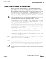
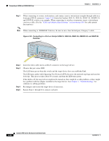
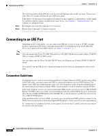
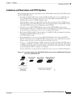
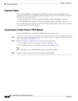
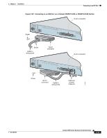
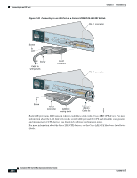
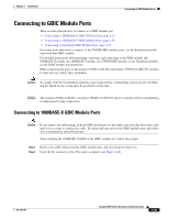
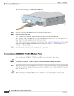
Connecting to an LRE Port Chapter 2 Installation Required Cables Connecting the LRE port to a patch panel or a POTS splitter requires a male-to-male RJ-21 cable, Category 3 or above. You can order RJ-21 cables from your cable vendor, or you can order these cables from your Cisco sales representative: • CAB-5-M120M120-5= (Category 5 cable with 90-degree, male-to-male RJ-21 connectors) • CAB-5-M180M120-5= (Category 5 cable with 120-degree, male-to-male RJ-21 connectors) The screws that you need to secure the cable to the switch are shipped with the cable. Contact your Cisco sales representative for more information. Connecting to a Patch Panel or POTS Splitter To connect the LRE port to a patch panel or POTS splitter, follow these steps: Step 1 Step 2 Connect one end of a cable connected to the wiring trunk to the RJ-21 connector (the LRE port) on the switch. (See Figure 2-38 and Figure 2-39.) Referring to Figure 2-38 and Figure 2-39, secure the cable to the switch: • For a 90-degree connector, see the top of Figure 2-38 and Figure 2-39. • For a 12-degree connector, see the bottom of Figure 2-38 and Figure 2-39. Note The cable tie is not included with the connector and cable assembly. Step 3 Connect the other end of the cable to the patch panel or POTS splitter. 2-32 Catalyst 2950 Switch Hardware Installation Guide OL-6156-01
-
 1
1 -
2
-
3
-
4
-
5
-
6
-
7
-
8
-
9
-
10
-
11
-
12
-
13
-
14
-
15
-
16
-
17
-
18
-
19
-
20
-
21
-
22
-
23
-
24
-
25
-
26
-
27
-
28
-
29
-
30
-
31
-
32
-
33
-
34
-
35
-
36
-
37
-
38
-
39
-
40
-
41
-
42
-
43
-
44
-
45
-
46
-
47
-
48
-
49
-
50
-
51
-
52
-
53
-
54
-
55
-
56
-
57
-
58
-
59
-
60
-
61
-
62
-
63
-
64
-
65
-
66
-
67
-
68
-
69
-
70
-
71
-
72
-
 73
73 -
 74
74 -
 75
75 -
 76
76 -
 77
77 -
 78
78 -
 79
79 -
 80
80 -
 81
81 -
 82
82 -
 83
83 -
84
-
85
-
86
-
87
-
88
-
89
-
90
-
91
-
92
-
93
-
94
-
95
-
96
-
97
-
98
-
99
-
100
-
101
-
102
-
103
-
104
-
105
-
106
-
107
-
108
-
109
-
110
-
111
-
112
-
113
-
114
-
115
-
116
-
117
-
118
-
119
-
120
-
121
-
122
-
123
-
124
-
125
-
126
-
127
-
128
-
129
-
130
-
131
-
132
-
133
-
134
 |
 |
