Cisco 2960 8TC Hardware Installation Guide - Page 48
Installing SFP Modules
 |
UPC - 882658120411
View all Cisco 2960 8TC manuals
Add to My Manuals
Save this manual to your list of manuals |
Page 48 highlights
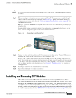
Installing and Removing SFP Modules Chapter 2 Switch Installation (24- and 48-Port Switches) stipulations for SFP module connections. Use only Cisco SFP modules on the Catalyst 2960 switch. Cisco SFP modules and the Catalyst 2960 switch support the Quality ID feature. Only SFP modules with the Quality ID feature are supported. For detailed instructions on installing, removing, and cabling the SFP module, refer to your SFP module documentation. Installing SFP Modules Figure 2-14 shows an SFP module that has a bale-clasp latch. Caution We strongly recommend that you do not install or remove the SFP module with fiber-optic cables attached to it because of the potential damage to the cables, the cable connector, or the optical interfaces in the SFP module. Disconnect all cables before removing or installing an SFP module. Removing and installing an SFP module can shorten its useful life. Do not remove and insert SFP modules more often than is absolutely necessary. Figure 2-14 SFP Module with a Bale-Clasp Latch 86575 Step 1 Attach an ESD-preventive wrist strap to your wrist and to a bare metal surface on the chassis. Step 2 Find the send (TX) and receive (RX) markings that identify the top side of the SFP module. Note On some SFP modules, the send and receive (TX and RX) markings might be replaced by arrows that show the direction of the connection, either send or receive (TX or RX). Step 3 Step 4 Align the SFP module in front of the slot opening. Insert the SFP module into the slot until you feel the connector on the module snap into place in the rear of the slot. See Figure 2-15. 2-16 Catalyst 2960 Switch Hardware Installation Guide OL-7075-09
-
 1
1 -
2
-
3
-
4
-
5
-
6
-
7
-
8
-
9
-
10
-
11
-
12
-
13
-
14
-
15
-
16
-
17
-
18
-
19
-
20
-
21
-
22
-
23
-
24
-
25
-
26
-
27
-
28
-
29
-
30
-
31
-
32
-
33
-
34
-
35
-
36
-
37
-
38
-
39
-
40
-
41
-
42
-
 43
43 -
 44
44 -
 45
45 -
 46
46 -
 47
47 -
 48
48 -
 49
49 -
 50
50 -
 51
51 -
 52
52 -
 53
53 -
54
-
55
-
56
-
57
-
58
-
59
-
60
-
61
-
62
-
63
-
64
-
65
-
66
-
67
-
68
-
69
-
70
-
71
-
72
-
73
-
74
-
75
-
76
-
77
-
78
-
79
-
80
-
81
-
82
-
83
-
84
-
85
-
86
-
87
-
88
-
89
-
90
-
91
-
92
-
93
-
94
-
95
-
96
-
97
-
98
-
99
-
100
-
101
-
102
-
103
-
104
-
105
-
106
-
107
-
108
 |
 |
