Cisco 3508G Installation Guide - Page 55
Collapsed Backbone and Switch Cluster Configuration
 |
UPC - 746320224237
View all Cisco 3508G manuals
Add to My Manuals
Save this manual to your list of manuals |
Page 55 highlights
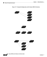
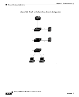
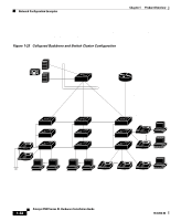
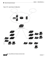
Chapter 1 Product Overview Network Configuration Examples Collapsed Backbone and Switch Cluster Configuration Figure 1-23 illustrates a configuration for a network of approximately 500 employees. This network uses a collapsed backbone and switch clusters. A collapsed backbone has high-bandwidth uplinks from all segments and subnetworks to a single device, such as a gigabit switch, which serves as a single point for monitoring and controlling the network. You can use a Catalyst 4908G-L3 switch, as illustrated, or a Catalyst 3508G XL switch to create a gigabit backbone. A Catalyst 4908G-L3 backbone switch provides the benefits of inter-VLAN routing and allows the router to focus on WAN access. The workgroups are created by clustering the Catalyst switches except the Catalyst 4908G-L3 switch. Using the Cisco Cluster Management Suite, you can group the switches into multiple clusters, as illustrated, or into a single cluster. You can manage a cluster through the IP address of its primary and secondary command switches, regardless of the geographic location of the cluster members. This network also includes voice and data subnetworks, where Cisco IP Phones are connected-using standard straight-through, twisted-pair cable with RJ-45 connectors-to the 10/100 inline-power ports on the Catalyst 3524-PWR XL switches and to the 10/100 ports on the Catalyst 3500 and 2900 XL switches. These multiservice switch ports automatically detect if an IP phone is connected. You also configure each port for 802.1p/Q QoS to give forwarding priority to voice traffic over data traffic. Cisco CallManager controls call processing, routing, and IP phone features and configuration. Users with workstations running Cisco SoftPhone software can place, receive, and control calls from their PCs. Using Cisco IP Phones, Cisco CallManager software, and Cisco SoftPhone software integrates telephony and IP networks, where the IP network supports both voice and data. Each 10/100 inline-power port on the Catalyst 3524-PWR XL switches provides -48V DC power to the Cisco IP Phone. The IP phone can receive redundant power when it also is connected to an AC power source. IP phones connected to switches other than the Catalyst 3524-PWR XL switches receive power from an AC power source. Grouping servers in a centralized location provides benefits such as security and easier maintenance. The gigabit connections to a server farm provide the workgroups full access to the network resources (such as a call-processing server running Cisco CallManager software, a Dynamic Host Configuration Protocol (DHCP)/Bootstrap Protocol (BOOTP) server, or an IPTV multicast server). 78-6456-04 Catalyst 3500 Series XL Hardware Installation Guide 1-31
-
 1
1 -
2
-
3
-
4
-
5
-
6
-
7
-
8
-
9
-
10
-
11
-
12
-
13
-
14
-
15
-
16
-
17
-
18
-
19
-
20
-
21
-
22
-
23
-
24
-
25
-
26
-
27
-
28
-
29
-
30
-
31
-
32
-
33
-
34
-
35
-
36
-
37
-
38
-
39
-
40
-
41
-
42
-
43
-
44
-
45
-
46
-
47
-
48
-
49
-
 50
50 -
 51
51 -
 52
52 -
 53
53 -
 54
54 -
 55
55 -
 56
56 -
 57
57 -
 58
58 -
 59
59 -
 60
60 -
61
-
62
-
63
-
64
-
65
-
66
-
67
-
68
-
69
-
70
-
71
-
72
-
73
-
74
-
75
-
76
-
77
-
78
-
79
-
80
-
81
-
82
-
83
-
84
-
85
-
86
-
87
-
88
-
89
-
90
-
91
-
92
-
93
-
94
-
95
-
96
-
97
-
98
-
99
-
100
-
101
-
102
-
103
-
104
-
105
-
106
-
107
-
108
-
109
-
110
-
111
-
112
-
113
-
114
-
115
-
116
-
117
-
118
-
119
-
120
-
121
-
122
-
123
-
124
-
125
-
126
-
127
-
128
-
129
-
130
-
131
-
132
-
133
-
134
-
135
-
136
-
137
-
138
-
139
-
140
-
141
-
142
-
143
-
144
-
145
-
146
-
147
-
148
-
149
-
150
-
151
-
152
-
153
-
154
-
155
-
156
-
157
-
158
-
159
-
160
 |
 |