Cisco 3550 12G Hardware Installation Guide
Cisco 3550 12G - Catalyst Switch - Stackable Manual
 |
UPC - 746320584911
View all Cisco 3550 12G manuals
Add to My Manuals
Save this manual to your list of manuals |
Cisco 3550 12G manual content summary:
- Cisco 3550 12G | Hardware Installation Guide - Page 1
Catalyst 3550 Multilayer Switch Hardware Installation Guide November 2004 Corporate Headquarters Cisco Systems, Inc. 170 West Tasman Drive San Jose, CA 95134-1706 USA http://www.cisco.com Tel: 408 526-4000 800 553-NETS (6387) Fax: 408 526-4100 Text Part Number: OL-6155-01 - Cisco 3550 12G | Hardware Installation Guide - Page 2
if not installed and used in accordance with the instruction manual, may cause harmful interference to radio communications. Operation relationship between Cisco and any other company. (0406R) Catalyst 3550 Multilayer Switch Hardware Installation Guide Copyright © 2004 Cisco Systems, Inc - Cisco 3550 12G | Hardware Installation Guide - Page 3
GBIC Module Slots 2-6 LEDs 2-6 System LED 2-6 RPS LED 2-7 Port LEDs and Modes 2-7 Rear-Panel Description 2-10 AC Power Connector 2-11 Cisco RPS Connector 2-11 Console Port 2-11 Management Options 2-11 Network Configurations 2-12 CONTENTS Catalyst 3550 Multilayer Switch Hardware Installation Guide - Cisco 3550 12G | Hardware Installation Guide - Page 4
3-5 Attaching Brackets to the Catalyst 3550-12T and 3550-12G Switches 3-6 Attaching Brackets to the Catalyst 3550-24, 3550-24-DC, 3550-24-FX, 3550-24PWR, and 3550-48 Switches 3-8 Mounting the Switch in a Rack 3-12 Wall Mounting 3-12 Attaching the Brackets to the Switch 3-13 Attaching the RPS - Cisco 3550 12G | Hardware Installation Guide - Page 5
Port D-2 Connecting to the Console Port D-2 Starting the Terminal-Emulation Software D-3 Powering on the Switch D-4 Entering the Initial Configuration Information D-4 IP Settings D-4 Completing the Setup Program D-5 Contents OL-6155-01 Catalyst 3550 Multilayer Switch Hardware Installation Guide - Cisco 3550 12G | Hardware Installation Guide - Page 6
Contents Catalyst 3550 Multilayer Switch Hardware Installation Guide vi OL-6155-01 - Cisco 3550 12G | Hardware Installation Guide - Page 7
the Catalyst 3550 Multilayer Switch Software Configuration Guide, the Catalyst 3550 Multilayer Switch Command Reference, the Catalyst 3550 Multilayer Switch System Message Guide, and the release notes on Cisco.com. For information about the standard Cisco IOS Release 12.2 commands, see the Cisco IOS - Cisco 3550 12G | Hardware Installation Guide - Page 8
des traductions des avertissements figurant dans les consignes de sécurité traduites qui accompagnent cet appareil, référez-vous au numéro de l'instruction situé à la fin de chaque avertissement. CONSERVEZ CES INFORMATIONS Catalyst 3550 Multilayer Switch Hardware Installation Guide viii OL-6155-01 - Cisco 3550 12G | Hardware Installation Guide - Page 9
encontrará el número que le ayudará a encontrar el texto traducido en el apartado de traducciones que acompaña a este dispositivo. GUARDE ESTAS INSTRUCCIONES OL-6155-01 Catalyst 3550 Multilayer Switch Hardware Installation Guide ix - Cisco 3550 12G | Hardware Installation Guide - Page 10
änd det nummer som finns i slutet av varje varning för att hitta dess översättning i de översatta säkerhetsvarningar som medföljer denna anordning. SPARA DESSA ANVISNINGAR Catalyst 3550 Multilayer Switch Hardware Installation Guide x OL-6155-01 - Cisco 3550 12G | Hardware Installation Guide - Page 11
. Brug erklæringsnummeret efter hver advarsel for at finde oversættelsen i de oversatte advarsler, der fulgte med denne enhed. GEM DISSE ANVISNINGER OL-6155-01 Catalyst 3550 Multilayer Switch Hardware Installation Guide xi - Cisco 3550 12G | Hardware Installation Guide - Page 12
Conventions Preface Catalyst 3550 Multilayer Switch Hardware Installation Guide xii OL-6155-01 - Cisco 3550 12G | Hardware Installation Guide - Page 13
Cisco.com) • Catalyst 3550 Switch Getting Started Guide (order number DOC-7816575=) • Regulatory Compliance and Safety Information for the Catalyst 3550 Switch (order number DOC-7816655 = For software information for the Catalyst 3550 switches, see these documents: • Catalyst 3550 Multilayer Switch - Cisco 3550 12G | Hardware Installation Guide - Page 14
tool: http://www.cisco.com/en/US/partner/ordering/ordering_place_order_ordering_tool_launch.html All users can order annual or quarterly subscriptions through the online Subscription Store: http://www.cisco.com/go/subscription Catalyst 3550 Multilayer Switch Hardware Installation Guide xiv OL-6155 - Cisco 3550 12G | Hardware Installation Guide - Page 15
the tools on the Cisco TAC website requires a Cisco.com user ID and password. If you have a valid service contract but do not have a login ID or password, register at this URL: http://tools.cisco.com/RPF/register/register.do OL-6155-01 Catalyst 3550 Multilayer Switch Hardware Installation Guide xv - Cisco 3550 12G | Hardware Installation Guide - Page 16
Technology Handbook, Internetworking Troubleshooting Guide, and the Internetworking Design Guide. For current Cisco Press titles and other information, go to Cisco Press online at this URL: http://www.ciscopress.com Catalyst 3550 Multilayer Switch Hardware Installation Guide xvi OL-6155-01 - Cisco 3550 12G | Hardware Installation Guide - Page 17
/ac147/about_cisco_the_internet_protocol_journal.html • Training-Cisco offers world-class networking training. Current offerings in network training are listed at this URL: http://www.cisco.com/en/US/learning/index.html OL-6155-01 Catalyst 3550 Multilayer Switch Hardware Installation Guide xvii - Cisco 3550 12G | Hardware Installation Guide - Page 18
Obtaining Additional Publications and Information Preface xviii Catalyst 3550 Multilayer Switch Hardware Installation Guide OL-6155-01 - Cisco 3550 12G | Hardware Installation Guide - Page 19
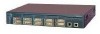
1 2 WS-C3550-12G 2 autosensing 10/100/1000 Ethernet ports 10 GBIC-based Gigabit module slots SYSTEM RPS MODE STATUS UTIL DUPLX SPEED 1 3 2 5 Catalyst 3550 4 7 6 9 11 8 12 10 1. GBIC = Gigabit Interface Converter 81594 OL-6155-01 Catalyst 3550 Switch Hardware Installation Guide - Cisco 3550 12G | Hardware Installation Guide - Page 20
Figure 1-2 Catalyst 3550-24, 3550-24-DC, 3550-FX, 3550-24PWR, and 3550-48 Switch Models Switch Description WS-C3550-24-SMI 24 autosensing 10/100 WS-C3550-24-EMI Ethernet ports 2 GBIC-based Gigabit module slots WS-C3550-24-DC- 24 autosensing 10/100 SMI Ethernet ports 2 GBIC-based Gigabit - Cisco 3550 12G | Hardware Installation Guide - Page 21
3550-48 switches) • 24 100BASE-FX ports (Catalyst 3550-24-FX switch) • Supports GBIC modules: - 1000BASE-SX - 1000BASE-LX/LX - 1000BASE-ZX - 1000BASE-T - GigaStack - CWDM • Supports Layer 3 routing (Catalyst 3550-12T and 3550-12G switches) • Supports optional Layer 3 routing (Catalyst 3550-24, 3550 - Cisco 3550 12G | Hardware Installation Guide - Page 22
• Support for fan-fault and overtemperature detection through the Network Assistant and the device manager. 1. Gigabit Interface Converter 2. Only Catalyst 3550-24PWR switch Front-Panel Description The switch front panel includes the 10/100 or 10/100/1000 Ethernet ports or 100BASE-FX ports, GBIC - Cisco 3550 12G | Hardware Installation Guide - Page 23
accordingly. 10/100 Inline Power Ports The 10/100 ports on the Catalyst 3550-24PWR switch provide protocol support for Cisco IP Phones and Cisco Aironet Access Points: • Provide -48 VDC power to all Cisco IP Phones and Cisco Aironet Access Points • Automatically detect a Cisco IP Phone or an access - Cisco 3550 12G | Hardware Installation Guide - Page 24
Network Assistant. The system LED shows whether the system is receiving power and is functioning properly. Table 1-2 lists the LED colors and their meanings. Table 1-2 System LED Color Off System Status System is not powered on. Catalyst 3550 Switch Hardware Installation Guide 1-6 OL-6155-01 - Cisco 3550 12G | Hardware Installation Guide - Page 25
internal power supply in a switch has failed, and the RPS is providing power to the switch (redundancy has been allocated to this device). For more information about the Cisco RPS 300 or the Cisco RPS 675, see the documentation included with the RPS. Port LEDs and Modes Each RJ-45 port and GBIC - Cisco 3550 12G | Hardware Installation Guide - Page 26
, the port LED is off even if the IP phone is connected to the switch port. The LED turns green only when the switch port is providing power. 1. Not available on Catalyst 3550-24PWR switches 2. Available only on Catalyst 3550-24PWR switches Catalyst 3550 Switch Hardware Installation Guide 1-8 OL - Cisco 3550 12G | Hardware Installation Guide - Page 27
12X 13 14 15 16 13X 17 18 19 20 21 22 23 24 15X 14X 16X < 25% + 25% - 49% + 50% + Catalyst 3550 SERIES 1 2 Figure 1-7 shows the bandwidth utilization percentages displayed by the LEDs on the Catalyst 3550-48 switch. OL-6155-01 Catalyst 3550 Switch Hardware Installation Guide 1-9 - Cisco 3550 12G | Hardware Installation Guide - Page 28
3550-12T switch as an example. All the Catalyst switches have similar components. Figure 1-9 Switch Rear Panel DC OUTPUT 1 100-240V~ 5-3A 50/60Hz 101604 1 1 RPS connector 2 AC power connector CONSOLE 23 4 3 Console port 4 Fan exhaust 1-10 Catalyst 3550 Switch Hardware Installation Guide - Cisco 3550 12G | Hardware Installation Guide - Page 29
675 has two output levels: -48 V and 12 V with a total maximum output power of 675 W. These Cisco RPS models support the Catalyst 3550 switches: • Cisco RPS 300 (model PWR300-AC-RPS-N1) supports the Catalyst 3550-12T, 3550-12G, 3550-24, 3550-FX, and 3550-48 switches. • Cisco RPS 675 (model PWR675-AC - Cisco 3550 12G | Hardware Installation Guide - Page 30
by generating switch-specific configuration changes, sending them to the switch, executing the configuration change, and logging the results. Network Configurations See the software configuration guide on Cisco.com for network configuration concepts and examples. 1-12 Catalyst 3550 Switch Hardware - Cisco 3550 12G | Hardware Installation Guide - Page 31
and Safety Information for the Catalyst 3550 Switch. Warning Only trained and qualified personnel should be allowed to install, replace, or service this equipment. Statement 1030 Warning Read the installation instructions before connecting the system to the power source. Statement 1004 Warning - Cisco 3550 12G | Hardware Installation Guide - Page 32
replacing power system (RPS) is not connected to the switch, install an RPS connector cover on the back of the switch. Statement 265 Warning To comply with safety regulations, mount switches on a wall with the front panel facing up. Statement 266 Catalyst 3550 Switch Hardware Installation Guide - Cisco 3550 12G | Hardware Installation Guide - Page 33
Chapter 2 Switch Installation Preparing for Installation Warning The Catalyst 3550-24-DC contains no field-replaceable units (FRUs). Do not open the chassis or attempt to remove or replace any components. For information about obtaining service for this unit, contact your reseller or Cisco sales - Cisco 3550 12G | Hardware Installation Guide - Page 34
3550-12T and 3550-12G switches) - Six Phillips flat-head screws for attaching the brackets to the switch (Catalyst 3550-24, 3550-24-DC, 3550-24-FX, 3550-24PWR, and 3550-48 switches) - Four Phillips machine screws for attaching the brackets to a rack Catalyst 3550 Switch Hardware Installation Guide - Cisco 3550 12G | Hardware Installation Guide - Page 35
the instructions described in these procedures: • Attaching Brackets to the Catalyst 3550-12T and 3550-12G Switches, page 2-6 • Attaching Brackets to the Catalyst 3550-24, 3550-24-DC, 3550-24-FX, 3550-24PWR, and 3550-48 Switches, page 2-8 • Mounting the Switch in a Rack, page 2-12 Note Installing - Cisco 3550 12G | Hardware Installation Guide - Page 36
Installing the Switch Chapter 2 Switch Installation Attaching Brackets to the Catalyst 3550-12T and 3550-12G Switches The bracket orientation and the brackets that you use depend on whether you are attaching the brackets for a 19-inch or a 24-inch rack. For 19-inch racks, use bracket part number - Cisco 3550 12G | Hardware Installation Guide - Page 37
19-Inch Racks, Rear Panel Forward Installing the Switch 19" Configuration Phillips flat-head screws Figure 2-4 Attaching Brackets for 24-Inch Racks, Rear Panel Forward 51365 24" Configuration Phillips flat-head screws 60914 OL-6155-01 Catalyst 3550 Switch Hardware Installation Guide 2-7 - Cisco 3550 12G | Hardware Installation Guide - Page 38
side. Note Before you attach the brackets on the Catalyst 3550-24-FX switch, remove the screws that are on the bottom-front of the chassis. Attach the bracket by using the supplied Phillips flat-head screws, as shown in Figure 2-7. Catalyst 3550 Switch Hardware Installation Guide 2-8 OL-6155-01 - Cisco 3550 12G | Hardware Installation Guide - Page 39
12X 19" Configuration Figure 2-8 Attaching Brackets for 24-Inch Racks, Front Panel Forward Phillips flat-head screws SYSTEM RPS MODE STATUS UTIL DUPLX SPEED 1 1X 23 45 67 8 9 10 11 12 11X 2X 12X 24" Configuration 60139 OL-6155-01 Catalyst 3550 Switch Hardware Installation Guide 2-9 - Cisco 3550 12G | Hardware Installation Guide - Page 40
for 19-Inch Racks, Rear Panel Forward CONSOLE 19" Configuration Phillips flat-head screws Figure 2-10 Attaching Brackets for 24-Inch Racks, Rear Panel Forward 49809 CONSOLE 24" Configuration Phillips flat-head screws 49810 2-10 Catalyst 3550 Switch Hardware Installation Guide OL-6155-01 - Cisco 3550 12G | Hardware Installation Guide - Page 41
Catalyst 3550 SERIES 2 19" Configuration Phillips flat-head screws Figure 2-12 Attaching Brackets for 24-Inch Telco Racks 1 Catalyst 3550 SERIES 2 24" Configuration Phillips flat-head screws 74036 Installing the Switch 74037 OL-6155-01 Catalyst 3550 Switch Hardware Installation Guide - Cisco 3550 12G | Hardware Installation Guide - Page 42
Cover, page 2-13 • Mounting the Switch on a Wall, page 2-14 Note The illustrations in this section show the Catalyst 3550-12T switch as an example. All the Catalyst 3550 switches are wall-mounted following the same procedures. 2-12 Catalyst 3550 Switch Hardware Installation Guide OL-6155-01 - Cisco 3550 12G | Hardware Installation Guide - Page 43
Figure 2-15 shows how to attach a 19-inch bracket to one side of the switch. Follow the same steps to attach the second bracket to the opposite side. Note On the Catalyst 3550-24-FX switch, remove the screws that are in the side of the chassis before you attach the brackets. Figure 2-15 Attaching - Cisco 3550 12G | Hardware Installation Guide - Page 44
facing up. Statement 266 Figure 2-17 Mounting the Switch on a Wall Catalyst 3550 11 12 1 2 3 4 5 6 7 8 9 10 MODE SPEEDDUPLX USTITLATUS RSPYSSTEM User-supplied screws 60967 User-supplied screws Table or Shelf Mounting Follow these steps to install the switch on a table or shelf: Step 1 Step - Cisco 3550 12G | Hardware Installation Guide - Page 45
can order a kit containing the ground lug and hardware from Cisco. For the Catalyst 3550-12G, 3550-24, and 3550-24-FX switches, order part number NEBS-LUG-3550=. Note When you install the ground-lug kit, you cannot connect an RPS to the switch. To install the ground lug, you need these tools and - Cisco 3550 12G | Hardware Installation Guide - Page 46
completes, the system LED is green. If the switch fails POST, the system LED is amber, and the port LED associated with the particular test is amber. If POST fails, see Chapter 3, "Troubleshooting," to determine a course of action. 2-16 Catalyst 3550 Switch Hardware Installation Guide OL-6155-01 - Cisco 3550 12G | Hardware Installation Guide - Page 47
the same AC power source. You can connect the Cisco RPS 300 (model PWR300-AC-RPS-N1) to these switch models: • Catalyst 3550-12T, 3550-12G, 3550-24, 3550-FX, or 3550-48 switch. (The Cisco RPS 300 does not support the Catalyst 3550-24-DC or 3550-24PWR switch.) Warning Attach only the Cisco RPS (model - Cisco 3550 12G | Hardware Installation Guide - Page 48
. Use the LAN-to-phone connector to connect the IP phone to the Catalyst 3550-24PWR switch. You can configure the 10/100 ports on the Catalyst 3550-24PWR switch to either automatically provide inline power when a Cisco IP Phone or a Cisco Aironet Access Point is connected or to never provide inline - Cisco 3550 12G | Hardware Installation Guide - Page 49
list of approved Gigabit Interface Converter (GBIC) modules and to your GBIC documentation for more information about installation, cabling, and configuring. See Related Publications, page xiii, for a list of related documentation. OL-6155-01 Catalyst 3550 Switch Hardware Installation Guide 2-19 - Cisco 3550 12G | Hardware Installation Guide - Page 50
Powering the Switch and Connecting Devices Chapter 2 Switch Installation 2-20 Catalyst 3550 Switch Hardware Installation Guide OL-6155-01 - Cisco 3550 12G | Hardware Installation Guide - Page 51
POST failures are usually fatal. Contact your Cisco representative if your switch does not pass POST. Note The LEDs on a Catalyst 3550-24PWR switch function differently during POST. Use the console port to view the POST results. Clearing the Switch IP Address and Configuration If you have configured - Cisco 3550 12G | Hardware Installation Guide - Page 52
: • Field notices • Security advisories • Troubleshooting resources • Factory defaults • Password recovery • Recovery from corrupted or missing software • Switch port problems • Network interface cards • Troubleshooting tools Catalyst 3550 Switch Hardware Installation Guide 3-2 OL-6155-01 - Cisco 3550 12G | Hardware Installation Guide - Page 53
the environmental requirements given in Appendix A, "Technical Specifications." - Make sure that the fan intake and exhaust areas are clear. • A fatal POST error is detected. See the "Understanding POST Results" section on page 3-1. OL-6155-01 Catalyst 3550 Switch Hardware Installation Guide 3-3 - Cisco 3550 12G | Hardware Installation Guide - Page 54
display the administrative and operational status of all ports or a specified port. • The cabling distance might be exceeded. Reduce the cable length to within the distances listed in the "Front-Panel Description" section on page 1-4. Catalyst 3550 Switch Hardware Installation Guide 3-4 OL-6155-01 - Cisco 3550 12G | Hardware Installation Guide - Page 55
Physical Specifications Dimensions (H x D x W) 32 to 113° F (0 to 45° C) -13 to 158° F (-25 to 70° C) 10 to 85% (noncondensing) Up to 10,000 ft (3049 m) Up to 15,000 ft (4573 m) Catalyst 3550-12T and 3550-12G: 16 lb (7.26 kg) Catalyst 3550-24: 11 lb (5 kg) Catalyst 3550-24-DC and 3550-24-FX: 10 - Cisco 3550 12G | Hardware Installation Guide - Page 56
Technical Specifications Table A-2 Power Requirements for the Catalyst 3550-12T, 3550-12G, 3550-24, 3550-24-FX, and 3550-48 Switches Power Requirements AC input voltage DC input voltages for RPS 300 Power Requirements DC input voltages for RPS 675 Power consumption Catalyst 3550-12T and 3550-12G - Cisco 3550 12G | Hardware Installation Guide - Page 57
Appendix A Technical Specifications Table A-5 Fiber-Port Specifications for Catalyst 3550-24-FX Switches Fiber-Port Power Levels Optical transmitter wavelength Optical receiver sensitivity for 50/125-micron cabling 1300 nm1 -33.5 to -11.8 dBm2 Optical receiver sensitivity for 62.5/125-micron - Cisco 3550 12G | Hardware Installation Guide - Page 58
Appendix A Technical Specifications Catalyst 3550 Multilayer Switch Hardware Installation Guide A-4 OL-6155-01 - Cisco 3550 12G | Hardware Installation Guide - Page 59
adapters that you use to connect the switch to other devices. Connector Specifications These sections describe the connectors used with the Catalyst 3550 switches. 10/100 and 10/100 /1000 Ports The 10/100 and 10/100/1000 Ethernet ports on Catalyst 3550 switches use standard RJ-45 connectors and - Cisco 3550 12G | Hardware Installation Guide - Page 60
described in Table B-2 and Table B-3. The supplied RJ-45-to-DB-9 adapter cable is used to connect the console port of the switch to a console PC. For console port and adapter pinout information, see Table B-2 and Table B-3. Catalyst 3550 Multilayer Switch Hardware Installation Guide B-2 OL-6155-01 - Cisco 3550 12G | Hardware Installation Guide - Page 61
when inline power is active. Figure B-6 Four Twisted-Pair Straight-Through Cable Schematic for 10/100 Ports Switch 1 RD+ 2 RD3 TD+ 6 TD- Router or PC 1 TD+ 2 TD3 RD+ 6 RD- 4 NC 5 NC 7 NC 8 NC 4 NC 5 NC 7 NC 8 NC 65271 OL-6155-01 Catalyst 3550 Multilayer Switch Hardware Installation Guide B-3 - Cisco 3550 12G | Hardware Installation Guide - Page 62
Four Twisted-Pair Crossover Cable Schematics for 10/100/1000 and 1000BASE-T GBIC Module Ports Switch 1 TPO+ 2 TPO3 TP1+ 6 TP1- Switch 1 TP0+ 2 TP03 TP1+ 6 TP1- 4 TP2+ 5 TP27 TP3+ 8 TP3- 4 TP2+ 5 TP27 TP3+ 8 TP3- 65274 Catalyst 3550 Multilayer Switch Hardware Installation Guide B-4 OL-6155-01 - Cisco 3550 12G | Hardware Installation Guide - Page 63
Console Port Signaling Using a DB-9 Adapter Switch Console Port (DTE) Signal RTS DTR TxD GND GND RxD DSR CTS RJ-45-to-DB-9 Terminal Adapter DB-9 Pin 8 6 2 5 5 3 4 7 Console Device Signal CTS DSR RxD GND GND TxD DTR RTS OL-6155-01 Catalyst 3550 Multilayer Switch Hardware Installation Guide B-5 - Cisco 3550 12G | Hardware Installation Guide - Page 64
adapter from Cisco. Table B-3 Console Port Signaling Using a DB-25 Adapter Switch Console Port (DTE) Signal RTS DTR TxD GND GND RxD DSR CTS RJ-45-to-DB-25 Terminal Adapter DB-25 Pin 5 6 3 7 7 2 20 4 Console Device Signal CTS DSR RxD GND GND TxD DTR RTS Catalyst 3550 Multilayer Switch Hardware - Cisco 3550 12G | Hardware Installation Guide - Page 65
Switch, page C-2 • Wiring the DC-Input Power Source, page C-4 Warning The Catalyst 3550-24-DC contains no field-replaceable units (FRUs). Do not open the chassis or attempt to remove or replace any components. For information about obtaining service for this unit, contact your reseller or Cisco - Cisco 3550 12G | Hardware Installation Guide - Page 66
mm), as shown in Figure C-1. Figure C-1 Stripping the Ground Wire 0.5 in. (12.7 mm) ± 0.02 in. (0.5 mm) 60528 Insulation Wire lead Step 3 Slide the open end of the ground lug over the exposed area of the 6-gauge wire. Catalyst 3550 Multilayer Switch Hardware Installation Guide C-2 OL-6155-01 - Cisco 3550 12G | Hardware Installation Guide - Page 67
to 15 lbf-in. (240 ozf-in.) Figure C-3 Torquing Ground-Lug Screws 36 1 - 72V 0.5A A B CONSOLE 65804 OL-6155-01 Torque to 15 lbf-in. Catalyst 3550 Multilayer Switch Hardware Installation Guide C-3 - Cisco 3550 12G | Hardware Installation Guide - Page 68
be allowed to install, replace, or service this equipment. Statement 1030 Warning Before performing any of the following procedures, ensure that power is removed from the DC circuit. Statement 1003 Caution You must connect the Catalyst 3550-24-DC switch only to a DC-input power source that has an - Cisco 3550 12G | Hardware Installation Guide - Page 69
. Warning An exposed wire lead from a DC-input power source can conduct harmful levels of electricity. Be sure that no exposed portion of the DC-input power source wire extends from the terminal block plug. Statement 122 OL-6155-01 Catalyst 3550 Multilayer Switch Hardware Installation Guide C-5 - Cisco 3550 12G | Hardware Installation Guide - Page 70
the Terminal-Block Captive Screws 60533 Torque to 4.5 lbf-in. (72 ozf-in.) Step 6 Repeat Steps 4 and 5 for the remaining three DC-input power source wires. Figure C-9 shows the completed wiring of a terminal block plug. Catalyst 3550 Multilayer Switch Hardware Installation Guide C-6 OL-6155-01 - Cisco 3550 12G | Hardware Installation Guide - Page 71
B Connecting to DC Power 60534 Step 7 Insert the terminal block plug in the terminal block header on the switch rear panel, as Catalyst 3550-24-DC switch is suitable only for intrabuilding or nonexposed wiring connections. OL-6155-01 Catalyst 3550 Multilayer Switch Hardware Installation Guide - Cisco 3550 12G | Hardware Installation Guide - Page 72
Connecting to DC Power Appendix C DC Power Connections Catalyst 3550 Multilayer Switch Hardware Installation Guide C-8 OL-6155-01 - Cisco 3550 12G | Hardware Installation Guide - Page 73
Setup, page D-1 • Accessing the CLI Through the Console Port, page D-2 Accessing the CLI Through Express Setup Express Setup is supported on switches running Cisco IOS Release 12.1(14)EA1 or later. If you are installing an unconfigured switch, see the Cisco IOS release label on the rear panel of the - Cisco 3550 12G | Hardware Installation Guide - Page 74
the supplied RJ-45-to-DB-9 adapter cable, insert the RJ-45 connector into the console port on the rear of the switch, as shown in Figure D-1. Attach the DB-9 female DTE of the adapter cable to the PC serial port, or attach an appropriate adapter to the terminal. Catalyst 3550 Multilayer Switch - Cisco 3550 12G | Hardware Installation Guide - Page 75
with the CLI-Based Setup Program Accessing the CLI Through the Console Port Figure D-1 Connecting a Switch Console Port to a PC 1 DC OUTPUT 1 2 100-240V~ 5-3A 50/60Hz CONSOLE 3 101825 1 Catalyst 3550 switch 2 Power cord 3 RJ-45-to-DB-9 adapter cable Starting the Terminal-Emulation Software - Cisco 3550 12G | Hardware Installation Guide - Page 76
this information from your network administrator before you complete the setup program: • Switch IP address • Subnet mask (IP netmask) • Default gateway (router) • Enable secret password • Enable password • Telnet password Catalyst 3550 Multilayer Switch Hardware Installation Guide D-4 OL-6155-01 - Cisco 3550 12G | Hardware Installation Guide - Page 77
is case sensitive, allows spaces, but ignores leading spaces. Enter virtual terminal password: terminal-password Step 6 (Optional) Configure SNMP by responding to the prompts. You can interface [255.0.0.0]: 255.255.255.0 OL-6155-01 Catalyst 3550 Multilayer Switch Hardware Installation Guide D-5 - Cisco 3550 12G | Hardware Installation Guide - Page 78
Save this configuration to nvram and exit. If you want to use the configuration the next time the switch reboots, save it in NVRAM by selecting option 2. Enter your selection [2]:2 Make your selection, and press Return. Catalyst 3550 Multilayer Switch Hardware Installation Guide D-6 OL-6155-01 - Cisco 3550 12G | Hardware Installation Guide - Page 79
port or through the network by using Telnet. For configuration information, see the switch software configuration guide or the switch command reference. To use the Network Assistant, see the Getting Started with Cisco Network Assistant guide. OL-6155-01 Catalyst 3550 Multilayer Switch Hardware - Cisco 3550 12G | Hardware Installation Guide - Page 80
Entering the Initial Configuration Information Appendix D Configuring the Switch with the CLI-Based Setup Program Catalyst 3550 Multilayer Switch Hardware Installation Guide D-8 OL-6155-01 - Cisco 3550 12G | Hardware Installation Guide - Page 81
2-5 Cisco Intelligence Engine 2100 See IE2100 Cisco IP Phones connecting to 3-18 support for 2-5 CiscoView 2-12 CLI accessing by using Express Setup D-1 accessing through console port D-2 described 2-12 command-line interface See CLI Catalyst 3550 Multilayer Switch Hardware Installation Guide IN - Cisco 3550 12G | Hardware Installation Guide - Page 82
cable See cables B-4 CWDM GBICs, described 2-6 D DC power connecting to C-1 to C-7 specifications A-2 warnings C-1 to C-5 Device Manager xiv description 2-12 diagnosing problems 4-2 dimensions A-1 documentation ordering xv related publications xiii to xiv URLs, Cisco xiv document conventions vii - Cisco 3550 12G | Hardware Installation Guide - Page 83
attaching 3-6 to 3-11 rack-mount 3-12 MT-RJ connector B-2 See also 100BASE-FX ports N Network Assistant getting started guide xiv Network Manager described 2-11 noise, electrical 3-4 notes, defined vii O obtaining documentation xv Catalyst 3550 Multilayer Switch Hardware Installation Guide IN-3 - Cisco 3550 12G | Hardware Installation Guide - Page 84
3-17 100BASE-FX cable lengths 2-5 connecting to 3-18 patch cables B-2 power levels A-3 power AC connector 2-10 connecting to 3-16, D-4 DC connector 2-10 IN-4 Catalyst 3550 Multilayer Switch Hardware Installation Guide RPS connector 2-10 specifications A-2 powering the switch 3-16 procedures - Cisco 3550 12G | Hardware Installation Guide - Page 85
technical specifications A-1 telco racks 3-5 temperature, operating A-1 terminal emulation software D-3 troubleshooting 4-1 to 4-4 U URLs, Cisco xiv W wall mounting 3-12 warnings defined vii installation 3-1 weight A-1 OL-6155-01 Catalyst 3550 Multilayer Switch Hardware Installation Guide IN-5 - Cisco 3550 12G | Hardware Installation Guide - Page 86
Index IN-6 Catalyst 3550 Multilayer Switch Hardware Installation Guide OL-6155-01
-
 1
1 -
 2
2 -
 3
3 -
 4
4 -
 5
5 -
 6
6 -
 7
7 -
8
-
9
-
10
-
11
-
12
-
13
-
14
-
15
-
16
-
17
-
18
-
19
-
20
-
21
-
22
-
23
-
24
-
25
-
26
-
27
-
28
-
29
-
30
-
31
-
32
-
33
-
34
-
35
-
36
-
37
-
38
-
39
-
40
-
41
-
42
-
43
-
44
-
45
-
46
-
47
-
48
-
49
-
50
-
51
-
52
-
53
-
54
-
55
-
56
-
57
-
58
-
59
-
60
-
61
-
62
-
63
-
64
-
65
-
66
-
67
-
68
-
69
-
70
-
71
-
72
-
73
-
74
-
75
-
76
-
77
-
78
-
79
-
80
-
81
-
82
-
83
-
84
-
85
-
86
 |
 |

Corporate Headquarters
Cisco Systems, Inc.
170 West Tasman Drive
San Jose, CA 95134-1706
USA
Tel: 408 526-4000
800 553-NETS (6387)
Fax: 408 526-4100
Catalyst 3550 Multilayer Switch
Hardware Installation Guide
November 2004
Text Part Number: OL-6155-01