Cisco 3750-48TS-S Hardware Installation Guide - Page 67
Verifying Package Contents - 3750g 24ts s switch
 |
UPC - 746320805184
View all Cisco 3750-48TS-S manuals
Add to My Manuals
Save this manual to your list of manuals |
Page 67 highlights
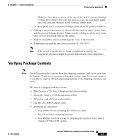
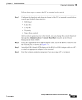
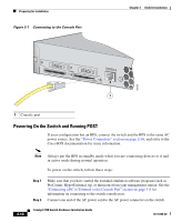
Chapter 3 Switch Installation Preparing for Installation Make sure that there is access to the rear of the rack if you are planning to stack the switches. If you do not have access to the rear panel, make sure you cable the switches before you rack mount them. - Rear-panel power connector is within reach of an AC power receptacle. • Cabling is away from sources of electrical noise, such as radios, power lines, and fluorescent lighting fixtures. Make sure the cabling is safely away from other devices that might damage the cables. • Airflow around the switch and through the vents is unrestricted. • Temperature around the unit does not exceed 113°F (45°C). Note If the switch is installed in a closed or multirack assembly, the temperature around it might be greater than normal room temperature. Verifying Package Contents Note Carefully remove the contents from the shipping container, and check each item for damage. If any item is missing or damaged, contact your Cisco representative or reseller for support. Return all packing material to the shipping container, and save it. The switch is shipped with these items: • This Catalyst 3750 Switch Hardware Installation Guide • About the Catalyst 3750 Documentation flyer • AC power cord (AC-powered switches) • One RJ-45-to-DB-9 adapter cable • Mounting kit containing: - Four rubber feet for mounting the switch on a table - Two 19-inch rack-mounting brackets - Four Phillips flat-head screws for attaching the brackets to the switch (Catalyst 3750G-24TS switch) 78-15136-02 Catalyst 3750 Switch Hardware Installation Guide 3-7
-
 1
1 -
2
-
3
-
4
-
5
-
6
-
7
-
8
-
9
-
10
-
11
-
12
-
13
-
14
-
15
-
16
-
17
-
18
-
19
-
20
-
21
-
22
-
23
-
24
-
25
-
26
-
27
-
28
-
29
-
30
-
31
-
32
-
33
-
34
-
35
-
36
-
37
-
38
-
39
-
40
-
41
-
42
-
43
-
44
-
45
-
46
-
47
-
48
-
49
-
50
-
51
-
52
-
53
-
54
-
55
-
56
-
57
-
58
-
59
-
60
-
61
-
 62
62 -
 63
63 -
 64
64 -
 65
65 -
 66
66 -
 67
67 -
 68
68 -
 69
69 -
 70
70 -
 71
71 -
 72
72 -
73
-
74
-
75
-
76
-
77
-
78
-
79
-
80
-
81
-
82
-
83
-
84
-
85
-
86
-
87
-
88
-
89
-
90
-
91
-
92
-
93
-
94
-
95
-
96
-
97
-
98
-
99
-
100
-
101
-
102
-
103
-
104
-
105
-
106
-
107
-
108
-
109
-
110
-
111
-
112
-
113
-
114
-
115
-
116
-
117
-
118
-
119
-
120
-
121
-
122
-
123
-
124
-
125
-
126
-
127
-
128
-
129
-
130
-
131
-
132
-
133
-
134
-
135
-
136
-
137
-
138
-
139
-
140
-
141
-
142
-
143
-
144
-
145
-
146
-
147
-
148
-
149
-
150
-
151
-
152
-
153
-
154
-
155
-
156
-
157
-
158
-
159
-
160
-
161
-
162
-
163
-
164
-
165
-
166
-
167
-
168
-
169
-
170
-
171
-
172
-
173
-
174
-
175
-
176
-
177
-
178
-
179
-
180
-
181
-
182
-
183
-
184
-
185
-
186
-
187
-
188
-
189
-
190
-
191
-
192
-
193
-
194
-
195
-
196
-
197
-
198
 |
 |