Cisco 3750G-24T Hardware Installation Guide
Cisco 3750G-24T - Catalyst Switch - Stackable Manual
 |
UPC - 746320805146
View all Cisco 3750G-24T manuals
Add to My Manuals
Save this manual to your list of manuals |
Cisco 3750G-24T manual content summary:
- Cisco 3750G-24T | Hardware Installation Guide - Page 1
Catalyst 3750 Switch Hardware Installation Guide October 2011 Americas Headquarters Cisco Systems, Inc. 170 West Tasman Drive San Jose, CA 95134-1706 USA http://www.cisco.com Tel: 408 526-4000 800 553-NETS (6387) Fax: 408 527-0883 Text Part Number: OL-6336-10 - Cisco 3750G-24T | Hardware Installation Guide - Page 2
generates, uses, and can radiate radio-frequency energy and, if not installed and used in accordance with the instruction manual, may Any use of actual IP addresses in illustrative content is unintentional and coincidental. Catalyst 3750 Switch Hardware Installation Guide © 2004-2011 Cisco Systems - Cisco 3750G-24T | Hardware Installation Guide - Page 3
-FX Ports 12 SFP Module Slots 12 SFP Modules 13 XENPAK Module Slot (Catalyst 3750G-16TD Switch) 13 LEDs 13 System LED 15 RPS LED 16 Master LED 16 Port LEDs and Modes 17 Rear Panel Description 21 StackWise Ports 24 Power Connectors 25 Internal Power Supply Connector 25 DC Power Connector 25 Cisco RPS - Cisco 3750G-24T | Hardware Installation Guide - Page 4
the Stack 8 Planning Considerations 8 Powering Considerations 8 Cabling Considerations 9 Recommended Cabling Configurations 10 Installing the Switch 11 Rack-Mounting 12 Removing Screws from the Switch 12 Attaching Brackets to the Catalyst 3750G-24TS Switch 14 Attaching Brackets to the Catalyst 3750G - Cisco 3750G-24T | Hardware Installation Guide - Page 5
and Configuration 6 Replacing a Failed Stack Member 6 Finding the Switch Serial Number 7 1 Technical Specifications 1 1 Connector and Cable Specifications 1 Connector Specifications 1 10/100 and 10/100/1000 Ports 2 100BASE-FX Ports 2 SFP Module Ports 3 XENPAK Module Ports (Catalyst 3750G-16TD Switch - Cisco 3750G-24T | Hardware Installation Guide - Page 6
2 Accessing the CLI Through the Console Port 2 Taking Out What You Need 3 Stacking the Switches (Optional) 4 Connecting to the Console Port 5 Starting the Terminal Emulation Software 6 Connecting to a Power Source 6 Entering the Initial Configuration Information 7 IP Settings 7 Completing the Setup - Cisco 3750G-24T | Hardware Installation Guide - Page 7
switch system message guide on the Cisco.com Product Documentation home page. For information about the standard Cisco IOS Release 12.1 or 12.2 commands, see the Cisco IOS documentation set from the Cisco.com home page by choosing Support > Documentation > Product and Support Documentation/Cisco IOS - Cisco 3750G-24T | Hardware Installation Guide - Page 8
available on the switch) • Cisco RPS 2300 Redundant Power System Hardware Installation Guide • Cisco RPS 675 Redundant Power System Hardware Installation Guide • Getting Started with Cisco Network Assistant • Cisco Small Form-Factor Pluggable Modules Installation Notes Catalyst 3750 Switch Hardware - Cisco 3750G-24T | Hardware Installation Guide - Page 9
100-Megabit Ethernet SFP Modules Compatibility Matrix • Cisco CWDM SFP Transceiver Compatibility Matrix • Cisco Small Form-Factor Pluggable Modules Compatibility Matrix • Compatibility Matrix for 1000BASE-T Small Form-Factor Pluggable Modules Obtaining Documentation, Obtaining Support, and Security - Cisco 3750G-24T | Hardware Installation Guide - Page 10
Obtaining Documentation, Obtaining Support, and Security Guidelines Preface Catalyst 3750 Switch Hardware Installation Guide x OL-6336-10 - Cisco 3750G-24T | Hardware Installation Guide - Page 11
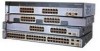
Catalyst 3750-24TS switch-24 10/100 Ethernet ports and 2 SFP module slots - Catalyst 3750-48TS switch-48 10/100 Ethernet ports and 4 SFP module slots - Catalyst 3750-24PS switch-24 10/100 Power over Ethernet (PoE) ports and 2 SFP module slots - Catalyst 3750-48PS switch-48 10/100 PoE ports and 4 SFP - Cisco 3750G-24T | Hardware Installation Guide - Page 12
switch-1.5 rack units (RU)-24 10/100/1000 Ethernet ports and 4 SFP module slots - Catalyst 3750G-24TS-1U switch-1 RU-24 10/100/1000 Ethernet ports and 4 SFP module slots - Catalyst 3750G-48TS switch-48 10/100/1000 Ethernet ports and 4 SFP module slots - Catalyst 3750G-24PS switch-24 10/100/1000 PoE - Cisco 3750G-24T | Hardware Installation Guide - Page 13
ports are not user-configurable. • Switches are hot-swappable. • Connection for an optional Cisco RPS 2300 or Cisco RPS 675 redundant power system (RPS) that operates on AC input and supplies backup DC power output to the Catalyst 3750 switches. The Catalyst 3750G-12S-SD switch does not support - Cisco 3750G-24T | Hardware Installation Guide - Page 14
-24TS and 3750V2-24TS Switch 86541 SYST RPS MASTR STAT DUPLX SPEED STACK MODE 12 1X 34 56 78 9 10 11 12 11X 2X 12X 13 14 13X 15 16 17 18 19 20 21 22 23 24 23X 14X 24X Catalyst 3750 SERIES 1 2 1 2 1 10/100 ports 2 SFP module slots Catalyst 3750 Switch Hardware Installation Guide - Cisco 3750G-24T | Hardware Installation Guide - Page 15
-24PS Switch 104577 SYST RPS STAT DUPLX SPEED PoE MODE 12 1X 34 56 78 9 10 11 12 11X 2X 12X 13 14 13X 15 16 17 18 19 20 21 22 23 24 23X Catalyst 3750 SERIES 14X 24X 1 2 1 2 1 10/100 PoE ports 2 SFP module slots OL-6336-10 Catalyst 3750 Switch Hardware Installation Guide - Cisco 3750G-24T | Hardware Installation Guide - Page 16
Figure 1-7 Catalyst 3750G-12S and 3750G-12S-SD Switch 97166 SYST RPS MASTR STAT DUPLX SPEED STACK MODE 1 2 3 4 5 6 7 8 Catalyst 3750 SERIES 9 10 11 12 1 1 SFP module slots Catalyst 3750-24T, 3750G-24TS, and 3750G-24TS-1U Switch Front Panel The 10/100/1000 ports on switch are grouped - Cisco 3750G-24T | Hardware Installation Guide - Page 17
15 16 17 18 19 20 21 22 23 24 23X 14X 24X Catalyst 3750 SERIES 25 26 27 28 1 2 1 10/100/1000 ports 2 SFP module slots Figure 1-10 Catalyst 3750G-24TS-1U Switch SYST RPS MASTR STAT DUPLX SPEED STACK MODE 12 1X 34 56 78 9 10 11 12 11X 2X 12X 13 14 13X 15 16 17 18 19 20 21 - Cisco 3750G-24T | Hardware Installation Guide - Page 18
Catalyst 3750G-24PS Switch 119769 SYST RPS MASTR STAT DUPLX SPEED STACK PoE MODE 12 1X 34 56 78 9 10 11 12 11X 2X 12X 13 14 13X 15 16 17 18 19 20 21 22 23 24 Catalyst 3750G SERIES PoE-24 23X 25 14X 27 24X 26 28 1 2 1 10/100/1000 PoE ports 2 SFP module slots Catalyst 3750 - Cisco 3750G-24T | Hardware Installation Guide - Page 19
. Figure 1-14 Catalyst 3750G-16TD Switch 104572 SYST RPS MASTR STAT DUPLX SPEED STACK MODE 12 1X 2X 34 56 78 9 10 11 12 13 14 15 16 15X 16X 1 TX RX Catalyst 3750 series 1 2 1 10/100/1000 ports 2 XENPAK module slot OL-6336-10 Catalyst 3750 Switch Hardware Installation Guide 1-9 - Cisco 3750G-24T | Hardware Installation Guide - Page 20
Catalyst 3750G-24WS-S25 and 3750G-24WS-S50 Switch 141726 SYST RPS MASTR STAT DUPLX SPEED STACK PoE 12 1X 34 56 78 9 10 11 12 11X 2X 12X 13 14 13X 15 16 17 18 19 20 21 22 23 24 23X 14X 24X CataWlyirset l3e7ss50LGASNERCIESoPntorEol-l2e4r 25 1 2 1 10/100/1000 PoE ports 2 SFP module - Cisco 3750G-24T | Hardware Installation Guide - Page 21
that do not support power-negotiation CDP. For information about configuring and monitoring PoE ports, see the device manager online help and the switch software configuration guide. Note You also can connect a Cisco IP Phone or Cisco Aironet Access Point to a Catalyst 3750 PoE switch 10/100 or - Cisco 3750G-24T | Hardware Installation Guide - Page 22
use either a crossover or a straight-through cable for connections to a copper 10/100, 10/100/1000, or 1000BASE-T SFP module port on the switch, no matter what type of device is on the other end of the connection. The auto-MDIX feature is enabled by default on switches running Cisco IOS Release 12 - Cisco 3750G-24T | Hardware Installation Guide - Page 23
B-4 for a list of XENPAK modules that the Catalyst 3750G-16TD switch supports. Note The 10-Gigabit Ethernet XENPAK modules are referred to as 10-Gigabit Ethernet module ports in the software documentation. LEDs You can use the switch LEDs to monitor switch activity and its performance. Figure - Cisco 3750G-24T | Hardware Installation Guide - Page 24
10/100/1000 Ports Figure 1-16 Switch LEDs (No PoE) SYST RPS MASTR STAT DUPLX SPEED STACK MODE 132966 12345678 1 Mode button 2 Stack LED 3 Speed LED 5 Status LED 6 Master LED 7 RPS LED1 4 Duplex LED 8 System LED 1. The RPS LED is not used on the Catalyst 3750G-12S-SD switch. Figure 1-17 - Cisco 3750G-24T | Hardware Installation Guide - Page 25
Chapter 1 Product Overview 10/100 and 10/100/1000 Ports Figure 1-18 Catalyst 3750G-24WS-S25 and 3750G-24WS-S50 Switch LEDs SYST RPS MASTR STAT DUPLX SPEED STACK PoE 141727 System LED 12345678 9 1 Mode button 2 PoE LED 3 Stack LED 4 Speed LED 5 Duplex LED 6 Status LED 7 Master LED 8 RPS LED - Cisco 3750G-24T | Hardware Installation Guide - Page 26
1-3 Master LED Port Mode Off Green Amber Description Switch is not the stack master. Switch is the stack master or a standalone switch. An error occurred when the switch was selecting the stack master switch or a stack error. 1-16 Catalyst 3750 Switch Hardware Installation Guide OL-6336-10 - Cisco 3750G-24T | Hardware Installation Guide - Page 27
Mode LEDs Mode LED STAT DUPLX SPEED STACK PoE Port Mode Port status Port duplex mode Port speed Stack member status StackWise port status 10/100 and 10/100/1000 PoE port power Description The port status. This is the default mode. The port duplex mode: full duplex or half duplex. Note The 10/100 - Cisco 3750G-24T | Hardware Installation Guide - Page 28
the 370 W switch power capacity. Blinking amber PoE is off due to a fault. STAT (port status) DUPLX (duplex) Caution PoE faults are caused when noncompliant cabling or powered devices are connected to a PoE port. Only standard-compliant cabling can be used to connect Cisco pre-standard IP Phones - Cisco 3750G-24T | Hardware Installation Guide - Page 29
. The PoE LED is on the Catalyst 3750-24PS, 3750G-24PS, 3750-48PS, 3750G-48PS, 3750G-24WS-S25 and 3750G-24WS-S50 switches. Even if PoE mode is not selected on the switches, this LED still shows PoE problems if they are detected. The Catalyst 3750G-S-SD does not have a PoE LED. The stack LED shows - Cisco 3750G-24T | Hardware Installation Guide - Page 30
3750G-24TS, 3750G-24TS-1U, and 3750G-24PS switches show the status for StackWise ports 1 and 2, respectively. • The 10/100/1000 port LEDs 23 and 24 on the Catalyst 3750G-24T switch show the status for StackWise ports 1 and 2, respectively. • SFP module port LEDs 11 and 12 on the Catalyst 3750G-12S - Cisco 3750G-24T | Hardware Installation Guide - Page 31
for the Catalyst 3750G-12S-SD switch), an RJ-45 console port, two StackWise ports, and a service port (only on the Catalyst 3750G Integrated Wireless LAN Controller switches). Figure 1-20 Catalyst 3750-24TS, 3750G-24T, 3750G-12S, 3750G-16TD, and 3750-48TS Switch 86548 STACK 1 STACK 2 CONSOLE - Cisco 3750G-24T | Hardware Installation Guide - Page 32
Figure 1-23 Catalyst 3750G-12S-SD Switch Rear Panel STACK 1 STACK 2 CONSOLE 336.0--712.V5A B- + A- + 1 23 4 5 1 StackWise ports 2 RJ-45 console port 3 Fan exhaust 4 DC power connector 5 Ground lug bracket 132634 1-22 Catalyst 3750 Switch Hardware Installation Guide OL-6336-10 - Cisco 3750G-24T | Hardware Installation Guide - Page 33
Figure 1-24 Catalyst 3750-24FS and 3750V2-FS Switch STACK 1 STACK 2 CONSOLE DSCPIENPCPOIUWFTIEESDRFISONURMPRPAELNYMUOATLE 1 23 1 StackWise ports 2 RJ-45 console port 3 Fan exhaust 4 5 4 RPS connector 5 AC power connector Figure 1-25 Catalyst 3750-24PS and 3750-48PS Switch STACK 1 STACK - Cisco 3750G-24T | Hardware Installation Guide - Page 34
1-26 Catalyst 3750G-24PS, 3750G-24TS-1U, 3750G-48PS, and 3750G-48TS Switch 119772 STACK 1 STACK 2 CONSOLE DSCPIENPCPOIUWFTIEESDRFISONURMPRPAELNYMUOATLE 1 23 1 StackWise ports 2 RJ-45 console port 3 Fan exhaust 4 5 4 RPS connector 5 AC power connector Figure 1-27 Catalyst 3750G-24WS-S25 - Cisco 3750G-24T | Hardware Installation Guide - Page 35
-STACK-3M= (3-meter cable) Power Connectors The switch is powered through the internal power supply. Except on the Catalyst 3750G-12S-SD switch, you can also connect the Cisco RPS 2300 or the Cisco RPS 675 to provide backup power should the switch internal power supply fail. Note The Catalyst 3750 - Cisco 3750G-24T | Hardware Installation Guide - Page 36
Options Chapter 1 Product Overview Cisco RPS 675 The Cisco RPS 675 has two output levels: -48 V and 12 V with a maximum output power of 675 W. Use the supplied RPS connector cable to connect the RPS to the switch. The RPS is a redundant power system that can support six external network devices - Cisco 3750G-24T | Hardware Installation Guide - Page 37
access the CLI either by connecting your management station directly to the switch console port or by using Telnet from a remote management station. See the Catalyst 3750 Switch Command Reference on Cisco.com for more information. • CiscoView application The CiscoView device-management application - Cisco 3750G-24T | Hardware Installation Guide - Page 38
Management Options Chapter 1 Product Overview 1-28 Catalyst 3750 Switch Hardware Installation Guide OL-6336-10 - Cisco 3750G-24T | Hardware Installation Guide - Page 39
Operation, page 2-7 • Planning the Stack, page 2-8 • Installing the Switch, page 2-11 • Connecting StackWise Cable to StackWise Ports, page 2-30 • Installing and Removing SFP Modules, page 2-33 • Installing and Removing XENPAK Modules (Catalyst 3750G-16TD Switch), page 2-35 • Connecting to the - Cisco 3750G-24T | Hardware Installation Guide - Page 40
370 Warning When the Catalyst 3750-12S switch and 100BASE-FX MMF small form-factor pluggable (SFP) module (model number GLC-GE-100FX) are running, the surface temperature of the removed SFP module might be hot. Statement 377 Catalyst 3750 Switch Hardware Installation Guide 2-2 OL-6336-10 - Cisco 3750G-24T | Hardware Installation Guide - Page 41
power is removed from the DC circuit. Statement 1003 Warning Read the installation instructions before connecting the system to the power all the Catalyst 3750 switches except the Catalyst 3750G-12S-SD switch. Warning To prevent bodily injury when mounting or servicing this unit in a rack, you - Cisco 3750G-24T | Hardware Installation Guide - Page 42
power supply connection. All connections must be removed to de-energize the unit. Statement 1028 Warning Only trained and qualified personnel should be allowed to install, replace, or service temperature of: 45•C Statement 1047 Catalyst 3750 Switch Hardware Installation Guide 2-4 OL-6336-10 - Cisco 3750G-24T | Hardware Installation Guide - Page 43
1089 NEBS standard, PoE or non-PoE 10/100/1000 Ethernet port cables that exit from either the left side or right side of the switch should be routed and tied to the nearest rack metal hardware. Note The grounding architecture of this product is DC-isolated (DC-I). Catalyst 3750G Integrated Wireless - Cisco 3750G-24T | Hardware Installation Guide - Page 44
1000BASE-ZX, and CWDM fiber-optic SFP module connections. Each port must match the wave-length specifications on the other end of the cable, and for reliable communications, the cable must not exceed the stipulated cable length. • See the Catalyst 3750 release notes for cable requirements for XENPAK - Cisco 3750G-24T | Hardware Installation Guide - Page 45
contact your Cisco representative or reseller for support. Tools and Equipment You need to supply a number-2 Phillips screwdriver to rack-mount the switch. Verifying Switch Operation Before you install the switch in a rack, on a wall, or on a table or shelf, you should power on the switch and verify - Cisco 3750G-24T | Hardware Installation Guide - Page 46
switch stacks, see the switch software configuration guide. Powering Considerations Consider the following guidelines before you power on the switches in a stack: • The sequence in which you initially power on the switches might affect the switch that becomes the stack master. Catalyst 3750 Switch - Cisco 3750G-24T | Hardware Installation Guide - Page 47
Managing Switch Stacks" chapter in the switch software configuration guide. Cabling Considerations The illustrations in this section display cabling configuration examples that show the stack bandwidth and possible stack partitioning. Figure 2-1 shows an example of a stack of Catalyst 3750 switches - Cisco 3750G-24T | Hardware Installation Guide - Page 48
Stacking the Switches in a Vertical Rack or on a Table Using the 0.5-meter StackWise Cable 86586 The configuration examples in Figure 2-6 use the 3-meter StackWise cable in addition to the supplied 0.5-meter StackWise cable. This configuration also provides redundant connections. 2-10 Catalyst - Cisco 3750G-24T | Hardware Installation Guide - Page 49
Stacking Nine Switches in a Side-by-Side Mounting Configuration 90532 Installing the Switch This section describes these installation procedures: • Rack-Mounting, page 2-12 • Wall-Mounting, page 2-27 • Table- or Shelf-Mounting, page 2-30 OL-6336-10 Catalyst 3750 Switch Hardware Installation Guide - Cisco 3750G-24T | Hardware Installation Guide - Page 50
hardware from Cisco. For the Catalyst 3750G-24TS switch, order part number RCKMNT-3550-1.5RU=. For the other Catalyst 3750 switches, order part number RCKMNT-1RU=. The Catalyst 3750G-24WS-S25 and the 3750G-24WS-S50 switch do not support 24-inch rack-mounting. Removing Screws from the Switch If you - Cisco 3750G-24T | Hardware Installation Guide - Page 51
from the Catalyst 3750G-24TS-1U, 3750G-24PS, 3750G-48PS, and 3750G-48TS Switch 126143 40 41 42 43 44 45 46 47 48 47X Catalyst 3750G SERIES 49 51 48X 50 52 Figure 2-11 Removing Screws from the Catalyst 3750G-12S and 3750-12S-SD Switch 97170 16 8 9 10 Catalyst 3750 SERIES 11 12 OL - Cisco 3750G-24T | Hardware Installation Guide - Page 52
24X CataWlyirset l3e7ss50LGASNERCIESoPntorEol-l2e4r 25 26 Attaching Brackets to the Catalyst 3750G-24TS Switch The bracket orientation and the brackets that you use depend on whether you are attaching the brackets for a 19-inch or a 24-inch rack. Figure 2-14 through Figure 2-19 show how to attach - Cisco 3750G-24T | Hardware Installation Guide - Page 53
Figure 2-15 Attaching Brackets for 24-Inch Racks, Front Panel Forward 1 13 14 15 16 13X 17 14X 86839 SYST RPS MASTR STAT DUPLX SPEED STACK MODE 1 Phillips flat-head screws 12 1X 34 56 78 9 10 11 12 11X 2X 12X 86557 OL-6336-10 Catalyst 3750 Switch Hardware Installation Guide 2-15 - Cisco 3750G-24T | Hardware Installation Guide - Page 54
@NUR1MP7RPAaELNYMUOATLE 1 1 Phillips flat-head screws Figure 2-18 Attaching Brackets for 19-Inch Telco Racks 86556 13 14 13X 15 16 17 18 19 20 21 22 23 24 23X 14X 24X Catalyst 3750 SERIES 25 26 27 28 2-16 Catalyst 3750 Switch Hardware Installation Guide 1 OL-6336-10 86558 - Cisco 3750G-24T | Hardware Installation Guide - Page 55
19-inch brackets on the Catalyst 3750G-24WS-S25 and the 3750G-24WS-S50 switches. Figure 2-20, Figure 2-21, and Figure 2-22 show how to attach the bracket to one side of the switch. Follow the same steps to attach the second bracket to the opposite side. For 19-inch racks, use part number 700-21419 - Cisco 3750G-24T | Hardware Installation Guide - Page 56
Catalyst 3750 switches: • Catalyst 3750-24TS, 3750V2-24TS, and 3750G-24TS • Catalyst 3750G-24T • Catalyst 3750-24FS and Catalyst 3750V2-24FS • Catalyst 3750G-12S and 3750G-12S-SD • Catalyst 3750-24PS, 3750V2-24PS, and 3750G-24PS • Catalyst 3750-48PS, 3750V2-48PS, and 3750G-48PS • Catalyst 3750G-16TD - Cisco 3750G-24T | Hardware Installation Guide - Page 57
to attach brackets for 19-inch racks in Figure 2-24 through Figure 2-27. These illustrations show how to attach each type of bracket to one side of the switch. Follow the same steps to attach the second bracket to the opposite side. OL-6336-10 Catalyst 3750 Switch Hardware Installation Guide 2-19 - Cisco 3750G-24T | Hardware Installation Guide - Page 58
-~60 HZ [email protected] 1 Phillips flat-head screws Figure 2-26 Attaching Brackets for 19-Inch Racks 16 8 9 10 Catalyst 3750 SERIES 11 12 1 Phillips truss-head screws 1 1 97171 86562 2-20 Catalyst 3750 Switch Hardware Installation Guide OL-6336-10 - Cisco 3750G-24T | Hardware Installation Guide - Page 59
for 23-Inch Racks, Front Panel Forward 132968 SYST RPS MASTR STAT DUPLX SPEED STACK MODE 1 Phillips flat-head screws Figure 2-29 Attaching Brackets for 23-Inch Racks, Rear Panel Forward 132969 1 Phillips flat-head screws OL-6336-10 1 Catalyst 3750 Switch Hardware Installation Guide 2-21 - Cisco 3750G-24T | Hardware Installation Guide - Page 60
-head screws Figure 2-31 Attaching Brackets for 24-Inch Racks, Rear Panel Forward 12 34 1X 5 2X 1.6A-100R>09A-A2T0,IN05GV0-~60 HZ [email protected] 1 1 Phillips flat-head screws 86563 2-22 Catalyst 3750 Switch Hardware Installation Guide OL-6336-10 - Cisco 3750G-24T | Hardware Installation Guide - Page 61
for ESTI Racks, Front Panel Forward 132970 SYST RPS MASTR STAT DUPLX SPEED STACK MODE 1 Phillips flat-head screws Figure 2-34 Attaching Brackets for ETSI Racks, Rear Panel Forward 132971 OL-6336-10 1 Phillips flat-head screws 1 Catalyst 3750 Switch Hardware Installation Guide 2-23 - Cisco 3750G-24T | Hardware Installation Guide - Page 62
to the switch, use the four supplied number-12 Phillips machine screws to securely attach the brackets to the rack, as shown in Figure 2-35, Figure 2-36 and Figure 2-37. Figure 2-35 Mounting the Catalyst 3750G-24TS Switch in a Rack 86566 SYST RPS MASTR STAT DUPLX SPEED STACK MODE 12 1X 34 - Cisco 3750G-24T | Hardware Installation Guide - Page 63
to a 10/100 or 10/100/1000 port and run Express Setup. See the Catalyst 3750 Switch Getting Started Guide for instructions. • Connect to the front-panel ports. See the "Connecting to the 10/100 and 10/100/1000 Ports" section on page 2-39 and the "Connecting to an SFP Module" section on page 2-41 to - Cisco 3750G-24T | Hardware Installation Guide - Page 64
in the rack. Use the supplied black screw, as shown in Figure 2-38, Figure 2-39 and Figure 2-40 to attach the cable guide to the left or right bracket. Figure 2-38 Attaching the Cable Guide on the 24-Port Catalyst 3750 Switches 86568 1 SYST RPS MASTR STAT DUPLX SPEED STACK MODE 12 1X 34 - Cisco 3750G-24T | Hardware Installation Guide - Page 65
front panel facing up: • Catalyst 3750-24FS, Catalyst 3750V2-24FS • Catalyst 3750-24TS, 3750-48TS, 3750-24PS, 3750-48PS • Catalyst 3750G-12S, 3750G-12S-SD • Catalyst 3750G-24T, 3750G-24TS, 3750G-24TS-1U • Catalyst 3750G-24PS, 3750G-48PS • Catalyst 3750G-16TD These switches wall-mount with the front - Cisco 3750G-24T | Hardware Installation Guide - Page 66
265 Figure 2-42 Attaching the RPS Connector Cover on the Switch 86571 STACK 1 STACK 2 CONSOLE [email protected] 1 2 3 1 Phillips pan-head screws 3 RPS connector 2 RPS connector cover 2-28 Catalyst 3750 Switch Hardware Installation Guide OL-6336-10 - Cisco 3750G-24T | Hardware Installation Guide - Page 67
the switches are stacked, see the "Planning Considerations" section on page 2-8 for information on powering considerations. • Connect to a 10/100 or 10/100/1000 port and run Express Setup. See the Catalyst 3750 Switch Getting Started Guide for instructions. OL-6336-10 Catalyst 3750 Switch Hardware - Cisco 3750G-24T | Hardware Installation Guide - Page 68
to a 10/100 or 10/100/1000 port and run Express Setup. See the Catalyst 3750 Switch Getting Started Guide for instructions. • Connect to the front-panel ports. See the "Connecting to the 10/100 and 10/100/1000 Ports" section on page 2-39 and the "Connecting to an SFP Module" section on page 2-41 to - Cisco 3750G-24T | Hardware Installation Guide - Page 69
use a Cisco-approved StackWise cable to connect the switches. Figure 2-44 Inserting the StackWise Cable in a StackWise Port STACK 1 STACK 2 CONSOLE 132362 Step 3 Use the window in the StackWise cable to align the connector correctly. Secure the screws tightly. Step 4 Insert the other end - Cisco 3750G-24T | Hardware Installation Guide - Page 70
a StackWise Port STACK 1 STACK 2 CONSOLE 86826 Caution Do not remove the cable by using the procedure shown in Figure 2-46. Figure 2-46 Incorrect Removal of a StackWise Cable from a StackWise Port STACK 1 STACK 2 CONSOLE 86827 2-32 Catalyst 3750 Switch Hardware Installation Guide OL - Cisco 3750G-24T | Hardware Installation Guide - Page 71
Catalyst 3750 switches. These field-replaceable modules provide uplink interfaces. You can use any combination of SFP modules. See the Catalyst 3750 release notes for the list of SFP modules that the Catalyst 3750 switch supports. Each port must match the wave-length specifications on the other end - Cisco 3750G-24T | Hardware Installation Guide - Page 72
rear of the slot. Figure 2-48 Installing an SFP Module into an SFP Module Slot 13 13X 5 6 7 14X 8 9 10 Catalyst 3750 SERIES 11 12 97169 Step 5 For fiber-optic SFP modules, remove the dust plugs from the optical ports, and store them for later use. Caution Do not remove the dust plugs from - Cisco 3750G-24T | Hardware Installation Guide - Page 73
-Clasp Latch SFP Module by Using a Flat-Blade Screwdriver 86554 13 X 14 15 16 17 18 19 20 21 22 23 24 23X X 24X Catalyst 3750 SERIES 1 2 1 1 Bale clasp Warning When the Catalyst 3750-12S switch and 100BASE-FX MMF small form-factor pluggable (SFP) module (model number GLC-GE-100FX) are - Cisco 3750G-24T | Hardware Installation Guide - Page 74
to as 10-Gigabit Ethernet module ports in the switch software documentation. See the Catalyst 3750 release notes for the list of XENPAK modules that the Catalyst 3750G-16TD switch supports. Use only Cisco XENPAK modules on the Catalyst 3750G-16TD switch. Each XENPAK module has an internal serial - Cisco 3750G-24T | Hardware Installation Guide - Page 75
the XENPAK module with the guide rails inside the module slot, and slide the module into the opening until the back of the XENPAK faceplate is flush with the switch faceplate. (See Figure 2-52.) Figure 2-52 Installing a XENPAK Module in the Catalyst 3750G-16TD Switch Catalyst 3750 series 1 TX - Cisco 3750G-24T | Hardware Installation Guide - Page 76
Installing and Removing XENPAK Modules (Catalyst 3750G-16TD Switch) Chapter 2 Switch Installation Removing a XENPAK Module To remove a XENPAK module, follow these steps: Step 1 Step 2 Step 3 Step 4 Step 5 Attach an ESD-preventive wrist strap to your wrist and to a bare metal surface on the - Cisco 3750G-24T | Hardware Installation Guide - Page 77
. Use the guidelines in Table 2-1 to select the correct cable for connecting the switch 10/100 and 10/100/1000 ports to other devices. See the "Cable and Adapter Specifications" section on page B-5 for cable-pinout descriptions. OL-6336-10 Catalyst 3750 Switch Hardware Installation Guide 2-39 - Cisco 3750G-24T | Hardware Installation Guide - Page 78
use either a crossover or a straight-through cable for connections to a copper 10/100, 10/100/1000, or 1000BASE-T SFP module port on the switch, regardless of the type of device on the other end of the connection. The auto-MDIX feature is enabled by default on switches running Cisco IOS Release 12 - Cisco 3750G-24T | Hardware Installation Guide - Page 79
Port SYST RPS MASTR STAT DUPLX SPEED STACK MODE 12 1X 34 56 78 9 10 11 12 11X 2X 12X 86818 Connecting to an SFP Module This section describes how to connect to SFP modules. • For instructions on how to connect to fiber-optic SFP modules, see the "Connecting to 1000BASE-T SFP Modules - Cisco 3750G-24T | Hardware Installation Guide - Page 80
. See Chapter 3, "Troubleshooting," for solutions to cabling problems. Figure 2-56 Connecting to an SFP Module Port 86550 13 13X 14 15 16 17 18 19 20 21 22 23 24 23X 14X 24X Catalyst 3750 SERIES 1 2 1 1 LC connector Step 5 If necessary, reconfigure and restart the switch or target - Cisco 3750G-24T | Hardware Installation Guide - Page 81
cable. Note When you connect the switch to a 1000BASE-T device, be sure to use a four twisted-pair, Category 5 or higher cable. Figure 2-57 Connecting to an SFP Module Port 13 13X 14 15 16 17 18 19 20 21 22 23 24 23X 14X 24X Catalyst 3750 SERIES 1 2 97348 1 1 RJ-45 connector Step - Cisco 3750G-24T | Hardware Installation Guide - Page 82
LED is off, the target device might not be turned on, there might be a cable problem, or there might be problem with the adapter installed in the target device. See Chapter 3, "Troubleshooting," for solutions to cabling problems. 2-44 Catalyst 3750 Switch Hardware Installation Guide OL-6336-10 - Cisco 3750G-24T | Hardware Installation Guide - Page 83
to a XENPAK Module Port 1 TX RX Catalyst 3750 series 1 104575 Where to Go Next 1 SC connector Step 6 If necessary, reconfigure and restart the switch or target device. Where to Go Next If the default configuration is satisfactory, the switch needs no further configuration. You can use any of - Cisco 3750G-24T | Hardware Installation Guide - Page 84
Where to Go Next Chapter 2 Switch Installation 2-46 Catalyst 3750 Switch Hardware Installation Guide OL-6336-10 - Cisco 3750G-24T | Hardware Installation Guide - Page 85
reference guide on Cisco.com, or the documentation that came with your SNMP application for details. This chapter describes these topics for troubleshooting problems: • Diagnosing Problems, page 3-1 • Clearing the Switch IP Address and Configuration, page 3-6 • Replacing a Failed Stack Member - Cisco 3750G-24T | Hardware Installation Guide - Page 86
and port type. Make sure that the ports on the connected device match and that they use the same type of encoding, optical frequency, and fiber type. For more information about cabling, see Appendix B, "Cable and Adapter Specifications." Catalyst 3750 Switch Hardware Installation Guide 3-2 OL - Cisco 3750G-24T | Hardware Installation Guide - Page 87
these items: • Bad or incorrect SFP module. Exchange the suspect module with a known, good module. Verify that this module supports this platform. See the "SFP Module Slots" section on page 1-12 for a list of supported SFP modules. OL-6336-10 Catalyst 3750 Switch Hardware Installation Guide 3-3 - Cisco 3750G-24T | Hardware Installation Guide - Page 88
Diagnosing Problems Chapter 3 Troubleshooting • Bad or incorrect XENPAK module. Replace the suspect module with a known good module. Verify that the platform supports the module. See the Table B-2 on page B-4 for a list of supported XENPAK modules. • Use the show interfaces privileged EXEC command - Cisco 3750G-24T | Hardware Installation Guide - Page 89
cards (NICs). By default, the switch ports and interfaces are set to autonegotiate. It is common for devices such as laptop computers or other devices to also be set to autonegotiate, yet sometimes autonegotation issues occur. To troubleshoot autonegotiation problems, try to manually set both sides - Cisco 3750G-24T | Hardware Installation Guide - Page 90
the member numbers for any members in the stack, you need to manually assign the replacement switch with the same member number as the failed switch. To assign the member number manually, see the switch software configuration guide. Catalyst 3750 Switch Hardware Installation Guide 3-6 OL-6336-10 - Cisco 3750G-24T | Hardware Installation Guide - Page 91
3750G-12S and 3750-12S-SD Switch Serial Number Location • Figure 3-3, Catalyst 3750G-16TD Switch Serial Number Location • Figure 3-4, Catalyst 3750-24PS Switch Serial Number Location • Figure 3-5, Catalyst 3750G-24PS and 3750G-24TS-1U Switches Serial Number Location • Figure 3-6, Catalyst 3750G-24TS - Cisco 3750G-24T | Hardware Installation Guide - Page 92
3750-12S-SD Switch Serial Number Location Figure 3-3 Catalyst 3750G-16TD Switch Serial Number Location Figure 3-4 Catalyst 3750-24PS Switch Serial Number Location Figure 3-5 Catalyst 3750G-24PS and 3750G-24TS-1U Switches Serial Number Location Catalyst 3750 Switch Hardware Installation Guide - Cisco 3750G-24T | Hardware Installation Guide - Page 93
3 Troubleshooting Finding the Switch Serial Number Figure 3-6 Catalyst 3750G-24TS Switch Serial Number Location Figure 3-7 Catalyst 3750-24TS and 3750V2-24TS Switch Serial Number Location Figure 3-8 Catalyst 3750-24PS and 3750V2-24PS Switch Serial Number Location OL-6336-10 Catalyst 3750 - Cisco 3750G-24T | Hardware Installation Guide - Page 94
Chapter 3 Troubleshooting Figure 3-9 Catalyst 3750G-24WS Switch Serial Number Location Figure 3-10 Catalyst 3750-48PS and 3750V2-48PS Switch Serial Number Location Figure 3-11 Catalyst 3750G-48PS and 3750G-48TS Switches Serial Number Location 119952, 781-00290-01 STACK 1 STACK 2 CONSOLE - Cisco 3750G-24T | Hardware Installation Guide - Page 95
Chapter 3 Troubleshooting Finding the Switch Serial Number Figure 3-12 Catalyst 3750-48TS and 3750V2-48TS Switch Serial Number Location OL-6336-10 Catalyst 3750 Switch Hardware Installation Guide 3-11 - Cisco 3750G-24T | Hardware Installation Guide - Page 96
Finding the Switch Serial Number Chapter 3 Troubleshooting 3-12 Catalyst 3750 Switch Hardware Installation Guide OL-6336-10 - Cisco 3750G-24T | Hardware Installation Guide - Page 97
on page A-6 • Specifications for the Catalyst 3750G-16TD Switch, Table A-10 on page A-6 • Specifications for the Catalyst 3750G-24TS Switch, Table A-11 on page A-7 • Specifications for the Catalyst 3750G-24TS-1U Switch, Table A-12 on page A-7 • Specifications for the Catalyst 3750-48TS Switch, Table - Cisco 3750G-24T | Hardware Installation Guide - Page 98
RPS 2300 and 675 +12 V @13 A Power consumption 120 W, 409 BTUs per hour Power rating 0.120 kVA Physical Dimensions Weight 10 lb (4.6 kg) Dimensions (H x W x D) 1.73 x 17.5 x 12.8 in. (4.4 x 44.5 x 32.6 cm) Table A-2 Specifications for the Catalyst 3750G-12S-SD Switch Environmental Ranges - Cisco 3750G-24T | Hardware Installation Guide - Page 99
and 675 +12 V @8.5 A Power consumption 70 W, 240 BTUs per hour Power rating 0.070 kVA Physical Dimensions Weight 9 lb (4.1 kg) Dimensions (H x W x D) 1.73 x 17.5 x 11.8 in. (4.4 x 44.5 x 30.1 cm) Table A-4 Specifications for the Catalyst 3750-24TS Switch Environmental Ranges Operating - Cisco 3750G-24T | Hardware Installation Guide - Page 100
and 675 +12 V @13 A Power consumption 165 W, 563 BTUs per hour Power rating 0.165 kVA Physical Dimensions Weight 10 lb (4.6 kg) Dimensions (H x W x D) 1.73 x 17.5 x 12.8 in. (4.4 x 44.5 x 32.6 cm) Table A-6 Specifications for the Catalyst 3750-24PS Switch Environmental Ranges Operating - Cisco 3750G-24T | Hardware Installation Guide - Page 101
DC input voltages for RPS 2300 and 675 +12 V @7.5 A and -48 V @7.8 A Power consumption 540 W Power dissipation 170 W, 580 BTUs per hour Power rating 0.54 kVA Power over Ethernet Range from 4 to 15.4 W per port, up to 370 W switch maximum Catalyst 3750 Switch Hardware Installation Guide A-5 - Cisco 3750G-24T | Hardware Installation Guide - Page 102
0.56 kVA Power over Ethernet Range from 4 to 15.4 W per port, up to 370 W switch maximum Physical Dimensions Weight 15.5 lb (7 kg) Dimensions (H x W x D) 1.73 x 17.5 x 16.1 in. (4.4 x 44.5 x 40.9 cm) Table A-10 Specifications for the Catalyst 3750G-16TD Switch Environmental Ranges Operating - Cisco 3750G-24T | Hardware Installation Guide - Page 103
2300 and 675 +12 V @17 A Power consumption 190 W, 650 BTUs per hour Power rating 0.190 kVA Physical Dimensions Weight 12.5 lb (5.7 kg) Dimensions (H x W x D) 2.59 x 17.5 x 11.6 in. (6.6 x 44.5 x 29.5 cm) Table A-12 Specifications for the Catalyst 3750G-24TS-1U Switch Environmental Ranges - Cisco 3750G-24T | Hardware Installation Guide - Page 104
A-12 Specifications for the Catalyst 3750G-24TS-1U Switch (continued) Environmental Ranges DC input voltages for RPS 2300 and 675 +12 V @10.5 A Power consumption 100 W Power dissipation 100 W, 314 BTUs per hour Power rating 0.10 kVA Physical Dimensions Weight 12 lb (5.5 kg) Dimensions - Cisco 3750G-24T | Hardware Installation Guide - Page 105
Power rating 0.52 kVA Power over Ethernet Range from 4 to 15.4 W per port, up to 370 W switch maximum Physical Dimensions Weight 21 lb (9.5 kg) Dimensions (H x W x D) 3.5 x 17.5 x 14.5in. (8.9 x 44.5 x 36.8 cm) Table A-16 Specifications for the Catalyst 3750V2-48PS and 3750V2-24PS Switch - Cisco 3750G-24T | Hardware Installation Guide - Page 106
voltages for RPS 2300 and 675 +12 V @17 A Power consumption 180 W, 615 BTUs per hour Power rating 0.180 kVA Physical Dimensions Weight 12.5 lb (5.7 kg) Dimensions (H x W x D) 1.73 x 17.5 x 11.6 in. (4.4 x 44.5 x 29.5 cm) A-10 Catalyst 3750 Switch Hardware Installation Guide OL-6336-10 - Cisco 3750G-24T | Hardware Installation Guide - Page 107
voltages for RPS 2300 and 675 +12 V @11.3 A Power consumption 55.2 W, 173 BTUs per hour Power rating 0.052 kVA Physical Dimensions Weight 9 lb (4.1 kg) Dimensions (H x W x D) 1.73 x 17.5 x 11.8 in. (4.4 x 44.5 x 30.1 cm) OL-6336-10 Catalyst 3750 Switch Hardware Installation Guide A-11 - Cisco 3750G-24T | Hardware Installation Guide - Page 108
Appendix A Technical Specifications A-12 Catalyst 3750 Switch Hardware Installation Guide OL-6336-10 - Cisco 3750G-24T | Hardware Installation Guide - Page 109
Connector Specifications These sections describe the connectors used with the Catalyst 3750 switches: • "10/100 and 10/100/1000 Ports" section on page B-2 • "100BASE-FX Ports" section on page B-2 • "SFP Module Ports" section on page B-3 • "XENPAK Module Ports (Catalyst 3750G-16TD Switch)" section - Cisco 3750G-24T | Hardware Installation Guide - Page 110
Appendix B Connector and Cable Specifications 10/100 and 10/100/1000 Ports The 10/100 and 10/100/1000 Ethernet ports on Catalyst 3750 switches use standard RJ-45 connectors and Ethernet pinouts with internal crossovers. Figure B-2 and Figure B-1 show the pinouts. Figure B-1 Pin 1 2 3 4 5 6 7 8 10 - Cisco 3750G-24T | Hardware Installation Guide - Page 111
Cisco Part Number CAB-MTRJ-SC-MM-1M CAB-MTRJ-SC-MM-3M CAB-MTRJ-SC-MM-5M CAB-MTRJ-ST-MM-1M CAB-MTRJ-ST-MM-3M CAB-MTRJ-ST-MM-5M SFP Module Ports The Catalyst 3750 switch uses SFP modules for fiber-optic and copper uplink ports. See the Catalyst 3750 release notes for a list of supported SFP modules - Cisco 3750G-24T | Hardware Installation Guide - Page 112
and Cable Specifications XENPAK Module Ports (Catalyst 3750G-16TD Switch) The Catalyst 3750G-16TD switch uses XENPAK modules for 10-Gigabit fiber-optic connections to networks. See the Catalyst 3750 release notes for a list of supported XENPAK modules. Fiber-optic XENPAK modules use SC connectors - Cisco 3750G-24T | Hardware Installation Guide - Page 113
length. Copper 1000BASE-T SFP transceivers use standard four twisted-pair, Category 5 or greater cable at lengths up to 328 feet (100 meters). Table B-3 Fiber-Optic SFP Module Port Cabling Specifications SFP Module 100BASE-BX (GLC-FE-100BX-D GLC-FE-100BX-U) 100BASE-FX (GLC-GE-100FX) 100BASE-FX - Cisco 3750G-24T | Hardware Installation Guide - Page 114
saturation, resulting in an elevated bit error rate (BER). When using the LX/LH SFP module with 62.5-micron diameter MMF, you must also install a mode-conditioning patch cord between the SFP module and the MMF cable on both the sending and receiving ends of the link. The mode-conditioning - Cisco 3750G-24T | Hardware Installation Guide - Page 115
+ 5 TP37 TP2+ 8 TP2- 65272 Figure B-10 Switch 1 TP0+ 2 TP03 TP1+ 6 TP1- 4 TP2+ 5 TP27 TP3+ 8 TP3- 65274 Four Twisted-Pair Crossover Cable Schematic for 10/100/1000 Ports Switch 1 TP0+ 2 TP03 TP1+ 6 TP1- 4 TP2+ 5 TP27 TP3+ 8 TP3- OL-6336-10 Catalyst 3750 Switch Hardware Installation Guide B-7 - Cisco 3750G-24T | Hardware Installation Guide - Page 116
on Catalyst 3750 switches. Figure B-12 Switch 1 TPO+ 2 TPO3 TP1+ 6 TP1- Four Twisted-Pair Straight-Through Cable Schematic for 10/100/1000 Ports Router or PC 1 TP1+ 2 TP13 TPO+ 6 TPO- 4 TP2+ 5 TP27 TP3+ 8 TP3- 4 TP3+ 5 TP37 TP2+ 8 TP2- 65272 Catalyst 3750 Switch Hardware Installation Guide - Cisco 3750G-24T | Hardware Installation Guide - Page 117
console port, RJ-45-to-DB-25 female DTE adapter, and the console device. Note The RJ-45-to-DB-25 female DTE adapter is not supplied with the switch. You can order a kit (part number ACS-DSBUASYN=) containing this adapter from Cisco. OL-6336-10 Catalyst 3750 Switch Hardware Installation Guide B-9 - Cisco 3750G-24T | Hardware Installation Guide - Page 118
B-5 Console Port Signaling Using a DB-25 Adapter Switch Console Port (DTE) Signal RTS DTR TxD GND GND RxD DSR CTS RJ-45-to-DB-25 Terminal Adapter DB-25 Pin 5 6 3 7 7 2 20 4 Console Device Signal CTS DSR RxD GND GND TxD DTR RTS B-10 Catalyst 3750 Switch Hardware Installation Guide OL-6336 - Cisco 3750G-24T | Hardware Installation Guide - Page 119
appendix describes how to make DC power connections to the Catalyst 3750G-12S-SD switch. See the "Installing the Switch" section on page 2-11 for instructions on installing the switch. Connecting to DC Power To connect the Catalyst 3750G-12S-SD switch to a DC-input power source, follow the steps in - Cisco 3750G-24T | Hardware Installation Guide - Page 120
the rear panel of the switch. (See Figure C-3 for location.) Use a standard Phillips screwdriver or a 12.7 mm) ± 0.02 in. (0.5 mm) 60528 Insulation Wire lead Step 3 Slide the open end of the ground lug over the exposed area of the 6-gauge wire. Catalyst 3750 Switch Hardware Installation Guide - Cisco 3750G-24T | Hardware Installation Guide - Page 121
Use either the front ground connector or the rear ground connector. You cannot use both at the same time. Figure C-3 Torquing Ground-Lug Screws STACK 1 STACK 2 CONSOLE 36 - 72V 3.0 - 1.5A B- + A- + 132635 1 Torque to 15 lbf-in. OL-6336-10 1 Catalyst 3750 Switch Hardware Installation Guide - Cisco 3750G-24T | Hardware Installation Guide - Page 122
and qualified personnel should be allowed to install, replace, or service this equipment. Statement 1030 Caution You must connect the Catalyst 3750G-12S-SD switch only to a DC-input power source that has an input supply voltage from -36 to -72 VDC. If the supply voltage is not in this range, the - Cisco 3750G-24T | Hardware Installation Guide - Page 123
and Negative Positions on the Switch Rear Panel 132976 STACK 1 STACK 2 CONSOLE 336.0--712.V5A B- + A- + 336.0--712.V5A B- + A- + Step 4 Using a 18-gauge wire- Power Source Wire 0.25 inch (6.3 mm) ± 0.02 inch (0.5 mm) 86460 OL-6336-10 Catalyst 3750 Switch Hardware Installation Guide C-5 - Cisco 3750G-24T | Hardware Installation Guide - Page 124
power source wire extends from the terminal block plug. Statement 122 Figure C-7 Inserting Wires in the Terminal Block Plug Return Negative Return Negative Feed A Feed B 60532 Step 6 Use maximum torque is 4.5 lbf-in. (72 ozf-in.) Catalyst 3750 Switch Hardware Installation Guide C-6 OL-6336-10 - Cisco 3750G-24T | Hardware Installation Guide - Page 125
-input power source switch rear panel, as shown in Figure C-10. Caution Secure the wires coming in from the terminal block so that they cannot be disturbed by casual contact. For example, use tie wraps to secure the wires to the rack. OL-6336-10 Catalyst 3750 Switch Hardware Installation Guide - Cisco 3750G-24T | Hardware Installation Guide - Page 126
surge requirements, intrabuilding wiring must be shielded, and the shield for the wiring must be grounded at both ends. Caution The Catalyst 3750G-12S-SD switch is suitable only for intrabuilding or nonexposed wiring connections. Catalyst 3750 Switch Hardware Installation Guide C-8 OL-6336-10 - Cisco 3750G-24T | Hardware Installation Guide - Page 127
or a switch stack. Before connecting the switch to a power source, review the safety warnings in Chapter 2, "Switch Installation." Note For detailed installation procedures on rack-mounting your switch, stacking your switches, or connecting to small form-factor pluggable (SFP) or XENPAK modules, see - Cisco 3750G-24T | Hardware Installation Guide - Page 128
then connecting an Ethernet port of the switch to the Ethernet port of your PC or workstation. To put the switch into Express Setup mode, follow the steps described in the Catalyst 3750 Switch Getting Started Guide for powering on the switch and using Express Setup. After the switch is in Express - Cisco 3750G-24T | Hardware Installation Guide - Page 129
use either a crossover or a straight-through cable for connections to a copper 10/100, 10/100/1000, or 1000BASE-T SFP module port on the switch, regardless of the type of device on the other end of the connection. The auto-MDIX feature is enabled by default on switches running Cisco IOS Release 12 - Cisco 3750G-24T | Hardware Installation Guide - Page 130
StackWise Cable to StackWise Ports" section on page 2-30 for detailed installation procedures on how to connect the switches in a stack. Figure D-3 Connecting the StackWise Cable to a StackWise Port STACK 1 STACK 2 CONSOLE 90530 Catalyst 3750 Switch Hardware Installation Guide D-4 OL-6336-09 - Cisco 3750G-24T | Hardware Installation Guide - Page 131
to perform the initial configuration. To connect the switch console port to a PC, use the supplied RJ-45-to-DB-9 adapter cable. Note If you have stacked your switches, connect to the console port of one of the switches in the stack. The initial configuration for the entire stack can be performed on - Cisco 3750G-24T | Hardware Installation Guide - Page 132
, the Status, the Duplex, the Speed, and the Stack LEDs turn green. (On the Power over Ethernet [PoE] switches, the PoE LED also turns green as POST begins.) The System LED flashes green, and the other LEDs remain continuous green. Catalyst 3750 Switch Hardware Installation Guide D-6 OL-6336-09 - Cisco 3750G-24T | Hardware Installation Guide - Page 133
. Would you like to enter the initial configuration dialog? [yes/no]: yes At any point you may enter a question mark '?' for help. Use ctrl-c to abort configuration dialog at any prompt. Default settings are in square brackets '[]'. OL-6336-09 Catalyst 3750 Switch Hardware Installation Guide D-7 - Cisco 3750G-24T | Hardware Installation Guide - Page 134
GUI. You can configure the switch as a command switch later through the CLI, the device manager, or the Network Assistant application. To configure it later, enter no. Would you like to enable as a cluster command switch? [yes/no]: no Catalyst 3750 Switch Hardware Installation Guide D-8 OL-6336-09 - Cisco 3750G-24T | Hardware Installation Guide - Page 135
by using telnet. For configuration information, see the switch software configuration guide or the switch command reference. To use the Network Assistant, see the Getting Started with Cisco Network Assistant guide on Cisco.com. OL-6336-09 Catalyst 3750 Switch Hardware Installation Guide D-9 - Cisco 3750G-24T | Hardware Installation Guide - Page 136
Entering the Initial Configuration Information Appendix D Configuring the Switch with the CLI-Based Setup Program D-10 Catalyst 3750 Switch Hardware Installation Guide OL-6336-09 - Cisco 3750G-24T | Hardware Installation Guide - Page 137
24-inch racks 12 5 A-branch circuit protection caution 4 A AC power connecting to 7 connector 25 specifications 2-8 adapter pinouts, terminal RJ-45-to-DB-25 9 RJ-45-to-DB-9 9 altitude, operating and storage 2-8 attaching the Cisco RPS warning 2, 7 autonegotiation 10 autonegotiation troubleshooting - Cisco 3750G-24T | Hardware Installation Guide - Page 138
-optic SFP modules 34 removing dust plugs from fiber-optic XENPAK modules 36 removing rubber plugs from SFP module 42 removing rubber plugs from XENPAK module 44 secure terminal block wires 7 torquing recommendation 6 using approved cables 24 Cisco enhanced power negotiation 11 Cisco IOS command - Cisco 3750G-24T | Hardware Installation Guide - Page 139
40 Cisco RPS See RPS CiscoView 27 Class 1 laser warning 3, 41, 44 CLI 27 accessing by using Express Setup 2 accessing through console port 2 code compliance warning 5 command-line interface See CLI connecting to 10/100 ports 39 to 10/100/1000 ports 39 to console port 4 to DC power 1-8 to SFP modules - Cisco 3750G-24T | Hardware Installation Guide - Page 140
5 Ethernet and fiber-optic cable troubleshooting 2 Express Setup using to access CLI 2 using to clear switch IP address 6 F features 1-3 front panel 10/100 ports 10 clearance 6 description 4-10 LEDs 13-19 SFP module ports 12-13 XENPAK module ports 2, 13, 4 G ground connection warning 4, 2 grounding - Cisco 3750G-24T | Hardware Installation Guide - Page 141
See also procedures installing SFP modules 33-34 installing XENPAK modules 36-37 J jewelry removal warning 2 L LEDs color meanings 17 duplex 17 front panel 14 interpreting 17 master 16 PoE 17 port 17-19 port mode 17-19 POST results 2 RPS 16 speed 17 stack 19 STATUS 17 system 15 troubleshooting with - Cisco 3750G-24T | Hardware Installation Guide - Page 142
9 SFP module ports 3 straight-through cables four twisted-pair 10/100 ports 7 four twisted-pair 1000BASE-T ports 8 two twisted-pair 10/100 ports 6 plug-socket accessibility warning 4 PoE faults caution 18, 40 high-powered devices 11 LED 17 shock hazard warning 5, 39 troubleshooting 3 port and - Cisco 3750G-24T | Hardware Installation Guide - Page 143
warning 4 publications, related viii R rack-mounting 12-30 rear panel clearance 6 description 21-26 redundant power supply See RPS removing SFP modules 34-35 removing XENPAK modules 38 restricted access area warning 4, 1 RJ-45 connector, console port 4 RJ-45 console port 21 RPS attachment warning - Cisco 3750G-24T | Hardware Installation Guide - Page 144
SNMP network management platforms 27 software switch management 26 specifications 1-9 speed, troubleshooting 5 stacking cabling considerations 9 connecting to a StackWise port 8 examples 8 planning considerations 8 powering considerations 8 stacking equipment warning 2 StackWise cable caution 31 - Cisco 3750G-24T | Hardware Installation Guide - Page 145
cable 2 connection problems 2 diagnosing problems 1 Ethernet and fiber-optic cables 2 link status 3 ping end device 4 PoE connections 3 port and interface settings 4 POST 1 spanning tree loops 4 speed, duplex, and autonegotiation 5 switch performance 5 with LEDs 2 troubleshooting spanning tree loops - Cisco 3750G-24T | Hardware Installation Guide - Page 146
RPS connector cover 2, 28 servicing equipment 4 shielding Ethernet cables 2 stacking equipment 2 wireless LAN controller 10 X XENPAK module rubber plugs warning 44 XENPAK modules 2, 13, 4 caution 36 connecting to 44-45 installation 36-37 removal 38 XENPAK modules caution 36
-
 1
1 -
 2
2 -
 3
3 -
 4
4 -
 5
5 -
 6
6 -
 7
7 -
8
-
9
-
10
-
11
-
12
-
13
-
14
-
15
-
16
-
17
-
18
-
19
-
20
-
21
-
22
-
23
-
24
-
25
-
26
-
27
-
28
-
29
-
30
-
31
-
32
-
33
-
34
-
35
-
36
-
37
-
38
-
39
-
40
-
41
-
42
-
43
-
44
-
45
-
46
-
47
-
48
-
49
-
50
-
51
-
52
-
53
-
54
-
55
-
56
-
57
-
58
-
59
-
60
-
61
-
62
-
63
-
64
-
65
-
66
-
67
-
68
-
69
-
70
-
71
-
72
-
73
-
74
-
75
-
76
-
77
-
78
-
79
-
80
-
81
-
82
-
83
-
84
-
85
-
86
-
87
-
88
-
89
-
90
-
91
-
92
-
93
-
94
-
95
-
96
-
97
-
98
-
99
-
100
-
101
-
102
-
103
-
104
-
105
-
106
-
107
-
108
-
109
-
110
-
111
-
112
-
113
-
114
-
115
-
116
-
117
-
118
-
119
-
120
-
121
-
122
-
123
-
124
-
125
-
126
-
127
-
128
-
129
-
130
-
131
-
132
-
133
-
134
-
135
-
136
-
137
-
138
-
139
-
140
-
141
-
142
-
143
-
144
-
145
-
146
 |
 |
Americas Headquarters
Cisco Systems, Inc.
170 West Tasman Drive
San Jose, CA 95134-1706
USA
Tel: 408 526-4000
800 553-NETS (6387)
Fax: 408 527-0883
Catalyst 3750 Switch
Hardware Installation Guide
October 2011
Text Part Number: OL-6336-10