Cisco 3750V2 Hardware Installation Guide - Page 56
Power Connectors, Internal Power Supply Connector, Cisco RPS Connector
 |
UPC - 882658269097
View all Cisco 3750V2 manuals
Add to My Manuals
Save this manual to your list of manuals |
Page 56 highlights
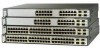
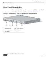
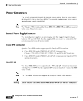
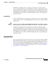
Rear Panel Description Chapter 2 Product Overview Power Connectors The switch is powered through the internal power supply. You can also connect the Cisco RPS 300 or the Cisco RPS 675 to provide backup power if the switch internal power supply should fail. Note The Catalyst 3750 switch and the Cisco RPS 300 or RPS 675 should be connected to the same AC power source. Internal Power Supply Connector The internal power supply is an autoranging unit that supports input voltages between 100 and 240 VAC. Use the supplied AC power cord to connect the AC power connector to an AC power outlet. Cisco RPS Connector Specific Cisco RPS modes support specific Catalyst 3750 switches: • Cisco RPS 300 (model PWR300-AC-RPS-N1) supports the Catalyst 3750-24TS, 3750G-24T, 3750G-12S, and 3750-48TS switches. • Cisco RPS 675 (model PWR675-AC-RPS-N1=) supports the Catalyst 3750 family of switches. Cisco RPS 300 The Cisco RPS 300 has two output levels: -48V and 12V with a total maximum output power of 300W. Use the supplied RPS connector cable to connect the RPS to the switch. Note The Cisco RPS 300 does not support the Catalyst 3750G-24TS switches. Warning Attach only the Cisco RPS (model PWR300-AC-RPS-N1) to the RPS receptacle. 2-16 Catalyst 3750 Switch Hardware Installation Guide 78-15136-02
-
 1
1 -
2
-
3
-
4
-
5
-
6
-
7
-
8
-
9
-
10
-
11
-
12
-
13
-
14
-
15
-
16
-
17
-
18
-
19
-
20
-
21
-
22
-
23
-
24
-
25
-
26
-
27
-
28
-
29
-
30
-
31
-
32
-
33
-
34
-
35
-
36
-
37
-
38
-
39
-
40
-
41
-
42
-
43
-
44
-
45
-
46
-
47
-
48
-
49
-
50
-
 51
51 -
 52
52 -
 53
53 -
 54
54 -
 55
55 -
 56
56 -
 57
57 -
 58
58 -
 59
59 -
 60
60 -
 61
61 -
62
-
63
-
64
-
65
-
66
-
67
-
68
-
69
-
70
-
71
-
72
-
73
-
74
-
75
-
76
-
77
-
78
-
79
-
80
-
81
-
82
-
83
-
84
-
85
-
86
-
87
-
88
-
89
-
90
-
91
-
92
-
93
-
94
-
95
-
96
-
97
-
98
-
99
-
100
-
101
-
102
-
103
-
104
-
105
-
106
-
107
-
108
-
109
-
110
-
111
-
112
-
113
-
114
-
115
-
116
-
117
-
118
-
119
-
120
-
121
-
122
-
123
-
124
-
125
-
126
-
127
-
128
-
129
-
130
-
131
-
132
-
133
-
134
-
135
-
136
-
137
-
138
-
139
-
140
-
141
-
142
-
143
-
144
-
145
-
146
-
147
-
148
-
149
-
150
-
151
-
152
-
153
-
154
-
155
-
156
-
157
-
158
-
159
-
160
-
161
-
162
-
163
-
164
-
165
-
166
-
167
-
168
-
169
-
170
-
171
-
172
-
173
-
174
-
175
-
176
-
177
-
178
-
179
-
180
-
181
-
182
-
183
-
184
-
185
-
186
-
187
-
188
-
189
-
190
-
191
-
192
-
193
-
194
-
195
-
196
-
197
-
198
 |
 |
