Cisco 7206 Network Configuration Guide - Page 91
Default Settings, Configuring Access and Trunk Interfaces
 |
UPC - 746320703879
View all Cisco 7206 manuals
Add to My Manuals
Save this manual to your list of manuals |
Page 91 highlights
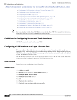
Chapter 3 Configuring Layer 2 Interfaces Default Settings Send document comments to [email protected] • Non-Cisco 802.1Q devices maintain only a single instance of spanning tree (the Mono Spanning Tree) that defines the spanning tree topology for all VLANs. When you connect a Cisco switch to a non-Cisco switch through an 802.1Q trunk, the Mono Spanning Tree of the non-Cisco switch and the native VLAN spanning tree of the Cisco switch combine to form a single spanning tree topology known as the Common Spanning Tree (CST). • Because Cisco devices transmit BPDUs to the SSTP multicast MAC address on VLANs other than the native VLAN of the trunk, non-Cisco devices do not recognize these frames as BPDUs and flood them on all ports in the corresponding VLAN. Other Cisco devices connected to the non-Cisco 802.1Q cloud receive these flooded BPDUs. This BPDU reception allows Cisco switches to maintain a per-VLAN spanning tree topology across a cloud of non-Cisco 802.1Q devices. The non-Cisco 802.1Q cloud that separates the Cisco devices is treated as a single broadcast segment between all devices connected to the non-Cisco 802.1Q cloud through 802.1Q trunks. • Make certain that the native VLAN is the same on all of the 802.1Q trunks that connect the Cisco devices to the non-Cisco 802.1Q cloud. • If you are connecting multiple Cisco devices to a non-Cisco 802.1Q cloud, all of the connections must be through 802.1Q trunks. You cannot connect Cisco devices to a non-Cisco 802.1Q cloud through access ports because doing so places the access port on the Cisco device into the spanning tree "port inconsistent" state and no traffic will pass through the port. • You can group trunk ports into port-channel groups, but all trunks in the group must have the same configuration. When a group is first created, all ports follow the parameters set for the first port to be added to the group. If you change the configuration of one of these parameters, the device propagates that setting to all ports in the group, such as the allowed VLANs and the trunk status. For example, if one port in a port group ceases to be a trunk, all ports cease to be trunks. • If you try to enable 802.1X on a trunk port, an error message appears, and 802.1X is not enabled. If you try to change the mode of an 802.1X-enabled port to trunk, the port mode is not changed. Default Settings Table 3-1 lists the default settings for device access and trunk port mode parameters. Table 3-1 Default Access and Trunk Port Mode Parameters Parameters Switchport mode Allowed VLANs Access VLAN ID Native VLAN ID Native VLAN ID tagging Administrative state Default Access 1 to 3967, 4048 to 4094 VLAN1 VLAN1 Disabled Shut Configuring Access and Trunk Interfaces This section includes the following topics: • Guidelines for Configuring Access and Trunk Interfaces, page 3-10 OL-23435-03 Cisco Nexus 7000 Series NX-OS Interfaces Configuration Guide, Release 5.x 3-9
-
 1
1 -
2
-
3
-
4
-
5
-
6
-
7
-
8
-
9
-
10
-
11
-
12
-
13
-
14
-
15
-
16
-
17
-
18
-
19
-
20
-
21
-
22
-
23
-
24
-
25
-
26
-
27
-
28
-
29
-
30
-
31
-
32
-
33
-
34
-
35
-
36
-
37
-
38
-
39
-
40
-
41
-
42
-
43
-
44
-
45
-
46
-
47
-
48
-
49
-
50
-
51
-
52
-
53
-
54
-
55
-
56
-
57
-
58
-
59
-
60
-
61
-
62
-
63
-
64
-
65
-
66
-
67
-
68
-
69
-
70
-
71
-
72
-
73
-
74
-
75
-
76
-
77
-
78
-
79
-
80
-
81
-
82
-
83
-
84
-
85
-
 86
86 -
 87
87 -
 88
88 -
 89
89 -
 90
90 -
 91
91 -
 92
92 -
 93
93 -
 94
94 -
 95
95 -
 96
96 -
97
-
98
-
99
-
100
-
101
-
102
-
103
-
104
-
105
-
106
-
107
-
108
-
109
-
110
-
111
-
112
-
113
-
114
-
115
-
116
-
117
-
118
-
119
-
120
-
121
-
122
-
123
-
124
-
125
-
126
-
127
-
128
-
129
-
130
-
131
-
132
-
133
-
134
-
135
-
136
-
137
-
138
-
139
-
140
-
141
-
142
-
143
-
144
-
145
-
146
-
147
-
148
-
149
-
150
-
151
-
152
-
153
-
154
-
155
-
156
-
157
-
158
-
159
-
160
-
161
-
162
-
163
-
164
-
165
-
166
-
167
-
168
-
169
-
170
-
171
-
172
-
173
-
174
-
175
-
176
-
177
-
178
-
179
-
180
-
181
-
182
-
183
-
184
-
185
-
186
-
187
-
188
-
189
-
190
-
191
-
192
-
193
-
194
-
195
-
196
-
197
-
198
-
199
-
200
-
201
-
202
-
203
-
204
-
205
-
206
-
207
-
208
-
209
-
210
-
211
-
212
-
213
-
214
-
215
-
216
-
217
-
218
-
219
-
220
-
221
-
222
-
223
-
224
-
225
-
226
-
227
-
228
-
229
-
230
-
231
-
232
-
233
-
234
-
235
-
236
-
237
-
238
-
239
-
240
-
241
-
242
-
243
-
244
-
245
-
246
-
247
-
248
-
249
-
250
-
251
-
252
-
253
-
254
-
255
-
256
-
257
-
258
-
259
-
260
-
261
-
262
-
263
-
264
-
265
-
266
-
267
-
268
-
269
-
270
-
271
-
272
-
273
-
274
-
275
-
276
-
277
-
278
-
279
-
280
-
281
-
282
-
283
-
284
-
285
-
286
-
287
-
288
-
289
-
290
-
291
-
292
-
293
-
294
-
295
-
296
-
297
-
298
-
299
-
300
-
301
-
302
-
303
-
304
-
305
-
306
-
307
-
308
 |
 |
