Cisco 888 G.SHDSL Router with 3G Hardware Installation Guide - Page 35
Connecting an IDSL Line, Connecting ISDN to Cisco 802 or Cisco 804 Routers
 |
UPC - 882658171611
View all Cisco 888 G.SHDSL Router with 3G manuals
Add to My Manuals
Save this manual to your list of manuals |
Page 35 highlights
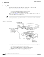
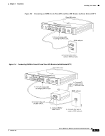
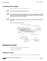
Chapter 2 Installation Figure 2-5 Connecting ISDN to Cisco 802 or Cisco 804 Routers Cisco 804 router Installing Your Router HUB NO HUB ETHERNET 10 BASE T 0 1 2 3 Cisco 804 CONSOLE ISDN U PHONE 1 2 1. Connect red cable to red ISDN U port. ISDN wall jack ISDN wall jack 11678 2. Connect other end of cable to ISDN wall jack. RJ-45-to-RJ-11 adapter cable If your wall jack has an RJ-11 connector, attach RJ-45-to-RJ-11 adapter cable to red cable, and then connect RJ-11 connector to ISDN wall jack. Connecting an IDSL Line Warning Network hazardous voltages are present in the IDSL cable. If you detach the IDSL cable, detach the end away from the router first to avoid possible electric shock. Network hazardous voltages also are present on the system card in the area of the IDSL port (RJ-45 connector), regardless of when power is turned to standby. Warning Do not work on the system or connect or disconnect cables during periods of lightning activity. Warning To reduce the risk of fire, use only No. 26 AWG or larger telecommunications line cord. Caution Always connect the red cable to the red IDSL port on the router. Do not connect the cable to a yellow Ethernet port. This will damage your router. Caution Cisco 802 IDSL and Cisco 804 IDSL routers do not support the Australian IUT requirement, which specifies that the routers must communicate for 1/2 hour after a power failure. If a power failure occurs, a Cisco 802 IDSL or 804 IDSL router stops communicating with other devices. 78-5373-04 Cisco 800 Series Routers Hardware Installation Guide 2-13
-
 1
1 -
2
-
3
-
4
-
5
-
6
-
7
-
8
-
9
-
10
-
11
-
12
-
13
-
14
-
15
-
16
-
17
-
18
-
19
-
20
-
21
-
22
-
23
-
24
-
25
-
26
-
27
-
28
-
29
-
 30
30 -
 31
31 -
 32
32 -
 33
33 -
 34
34 -
 35
35 -
 36
36 -
 37
37 -
 38
38 -
 39
39 -
 40
40 -
41
-
42
-
43
-
44
-
45
-
46
-
47
-
48
-
49
-
50
-
51
-
52
-
53
-
54
-
55
-
56
-
57
-
58
-
59
-
60
-
61
-
62
-
63
-
64
-
65
-
66
-
67
-
68
-
69
-
70
 |
 |
