Cisco AIR-ANT1949 User Guide - Page 7
Suggested Cable - aironet yagi antenna
 |
View all Cisco AIR-ANT1949 manuals
Add to My Manuals
Save this manual to your list of manuals |
Page 7 highlights
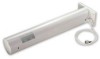
Installation Notes Follow these instructions to mount the antenna on a mast. Step 1 Step 2 Step 3 Attach the U-bolts, clamps, and backing plate to the antenna as shown in Figure 1. Install a washer and start a locknut on each U-bolt. Position the loose mounting assembly over the mast. Note To ensure correct antenna polarization orientation, make sure the arrows on the antenna are pointed up. Step 4 Step 5 Use a 7/16-in (11.1-mm) wrench or suitable adjustable wrench to secure the assembly to the mast. Tighten the locknuts to a point where the antenna does not slide down the mast but is loose enough for you to rotate. Rotate the antenna until it points towards the other WLAN antenna your wireless device is to communicate with. Note The accuracy of the orientation should be within 15 degrees to achieve maximum gain. This is especially important if the path length is over 1 mile (1.6 kilometers). If you use this antenna to connect to several terminals, aim it in the general direction of the group. If the paths are not obstructed or are less than 1 mile (1.6 kilometers), this arrangement should work well. Step 6 Tighten the locknuts. Note Tighten the locknuts evenly and do not exceed 45 in-lbs of torque on the locknuts. Step 7 Secure the antenna cable to the mast with cable ties or electrical tape. Step 8 Apply the danger label to a plainly visible area of the antenna support structure. Note The antenna is not DC grounded. It is recommended that you install lightning-protection devices in your system. See the Installation Instructions for Cisco Aironet Lightning Arrestors. This document is available on the World Wide Web at the following URL: http://www.cisco.com/en/US/docs/wireless/lightning_arrestor/installation/guide/hslar.htm l Suggested Cable Cisco recommends a high-quality, low-loss cable for use with the antenna. Note The higher the frequency, the greater the loss through the cable. Also, the longer the run, the greater the loss. The antenna terminates with a RP-TNC plug after a short, 3-ft (0.91-m) cable. The mating connector to the antenna is an appropriate RP-TNC jack. The connector on the opposite end will vary according to the type of equipment used. 78-14720-02 Cisco Aironet 13.5-dBi Yagi Mast Mount Antenna (AIR-ANT1949) 7
-
 1
1 -
 2
2 -
 3
3 -
 4
4 -
 5
5 -
 6
6 -
 7
7 -
 8
8
 |
 |
